Fan, motor and impeller thereof

a technology of motor and impeller, which is applied in the direction of magnetic circuit rotating parts, piston pumps, magnetic circuit shapes/forms/construction, etc., can solve the problems of increasing unstable heat-aggravated phenomena that influence product reliability, poor heat-dissipation effect, and the efficiency of the fan b>1/b> may deteriorate, so as to enhance the operation efficiency of the fan and the effect of the motor and the impeller

Active Publication Date: 2007-09-06
DELTA ELECTRONICS INC
View PDF4 Cites 19 Cited by
  • Summary
  • Abstract
  • Description
  • Claims
  • Application Information

AI Technical Summary

Benefits of technology

[0013]As mentioned above, the airflow passage is formed between the inner wall of the hub and the conducting shell in the fan, the motor and the impeller thereof according to the invention. The heat generated by the operating stator can be transferred, via the conducting shell, to the airflow flowing through the airflow passage. The heat is then drawn out of the fan, the motor and the impeller via the air gap by the airflow so that the dissipation effect on self-produced heat

Problems solved by technology

Due to this trend, there is also an increase in unstable heat-aggravated phenomena that influence product reliability.
However, this causes the heat dissipated by the motor 12 to be restricted to the hub 111 and thus the heat-dissipating effect is poor.
Thus, the ef

Method used


Image

  • Fan, motor and impeller thereof
  • Fan, motor and impeller thereof
  • Fan, motor and impeller thereof

Examples


Embodiment Construction

[0021]The present invention will be apparent from the following detailed description, which proceeds with reference to the accompanying drawings, wherein the same references relate to the same elements.

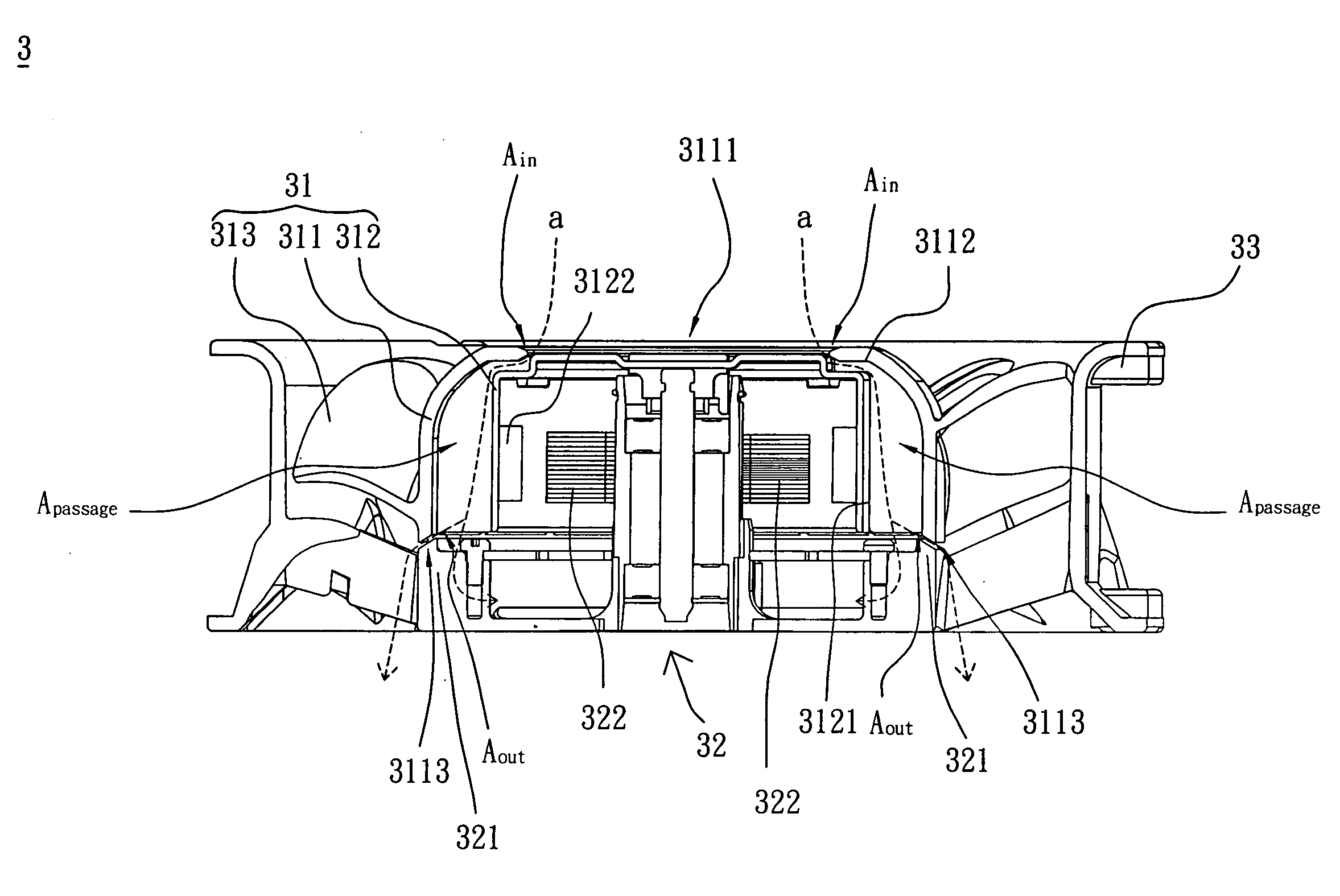
[0022]Referring to FIG. 3, a fan 3 according to a first embodiment of the invention includes a rotor 31, a stator 32 and a frame 33. The rotor 31 and the stator 32 are disposed in the frame 33, and the rotor 31 is driven by the stator 32. In this embodiment, the rotor 31 includes a hub 311, a conducting shell 312 and a plurality of blades 313. The conducting shell 312 covers at least one side of the stator 32. The hub 311 is coupled to the conducting shell 312. The blades 313 are disposed around the hub 311.

[0023]In this embodiment, the blades 313 and the hub 311 can be integrally formed as a single piece or individually formed and then assembled together. The blades 313 may be centrifugal blades, axial flowing blades, flat blades or curved blades. The hub 311 can be cylindrical, poly...


PUM


Abstract

An impeller, which is driven by a stator, includes a conducting shell, a hub and a plurality of blades. The conducting shell covers at least one side of the stator. The hub covers the conducting shell. At least one air gap is formed between the hub and the stator. A top portion of the hub has an opening to partially expose a top portion of the conducting shell. At least one airflow passage is formed between an inner wall of the hub and an outer surface of the conducting shell. The airflow passage has at least one inlet connected with the opening and at least one outlet connected with the air gap. The blades are disposed around the circumferences of the hub.

Description

CROSS REFERENCE TO RELATED APPLICATIONS[0001]This Non-provisional application claims priority under 35 U.S.C. §119(a) on Patent Application No(s). 095107178 filed in Taiwan, Republic of China on Mar. 3, 2006, the entire contents of which are hereby incorporated by reference.BACKGROUND OF THE INVENTION[0002]1. Field of Invention[0003]The invention relates to a fan, a motor and an impeller, and, in particular, to a fan, a motor and an impeller with good heat dissipation ability.[0004]2. Related Art[0005]With the rapid development of electronic products toward increasing performance, frequency, and speed, as well as increasing demand for compact, slim-profile, lightweight devices, the operating temperature of electronic products is correspondingly increasing. Due to this trend, there is also an increase in unstable heat-aggravated phenomena that influence product reliability. Therefore, current electronic products are often equipped with a fan that serves as a heat-dissipation device.[...

Claims


Application Information

Patent Timeline
IPC IPC(8): H02K9/00H02K7/00F04B17/00
CPCF04D25/0613H02K9/14F04D25/082F04D29/5806
Inventor LAN, CHUNG-KAICHEN, HUNG-CHIHUANG, WEN-SHI
Owner DELTA ELECTRONICS INC
Why Eureka
Try Eureka