Adaptive cycle-slipped detector for unlock detection in phase-locked loop applications

a detector and phase-locked loop technology, applied in the field of phase-locked loops, can solve problems such as reducing the window of allowable phase offs

Active Publication Date: 2007-09-06
KEYSIGHT TECH
View PDF1 Cites 26 Cited by
  • Summary
  • Abstract
  • Description
  • Claims
  • Application Information

AI Technical Summary

Problems solved by technology

Unfortunately, there are several problems that may occur when utilizing a CSD to determine when a PLL circuit locks.
An additional problem is that the two input signals to the CSD must be phase offset to avoid simultaneous clocking.
This problem is aggravated when fractional division implemented with dithering is used, further reducing the window of allowable phase offset.

Method used


Image

  • Adaptive cycle-slipped detector for unlock detection in phase-locked loop applications
  • Adaptive cycle-slipped detector for unlock detection in phase-locked loop applications
  • Adaptive cycle-slipped detector for unlock detection in phase-locked loop applications

Examples


Embodiment Construction

[0021] In the following description of the preferred embodiment, reference is made to the accompanying drawings that form a part hereof, and which show, by way of illustration, a specific embodiment in which the invention may be practiced. Other embodiments may be utilized and structural changes may be made without departing from the scope of this invention.

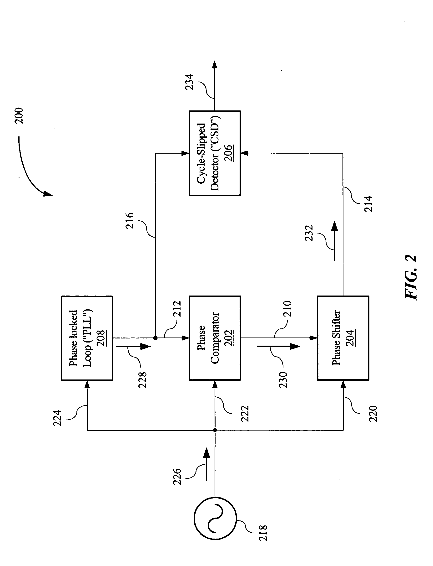
[0022] In FIG. 2, a block diagram of an example of an implementation of an adaptive cycle-slipped detector (“ACSD”) 200 is shown. The ACSD 200 may include a phase comparator 202, phase shifter 204, and a cycle-slipped detector (“CSD”) 204. The phase comparator 202 may be in signal communication with the phase shifter 206 and a phase locked loop (“PLL”) circuit 208 via signal paths 210 and 212, respectively. The CSD 206 may be in signal communication with the phase shifter 204 and PLL circuit 208 via signal paths 214 and 216, respectively. In this example, the phase comparator 202, phase shifter 204, and PLL circuit 208 may be in...


PUM


Abstract

An adaptive cycle-slipped detector (“ACSD”) for use in a Phase-Locked Loop (“PLL”) circuit. The ACSD may include a phase comparator, a phase shifter in signal communication with the phase comparator, and a cycle-slipped detector (“CSD”) in signal communication with the phase shifter.

Description

BACKGROUND OF THE INVENTION [0001] A Phase-Locked Loop (“PLL”) device is basically a closed loop frequency control system that compares the phase and frequency of two signals, a reference signal and a feedback signal, and produces an error signal that is proportional to the difference between these two signals. PLL circuits may be used in many applications, with the initial applications being in radio television receivers. With the development of low-cost integrated circuit (“IC”) packages, the PLL principle has been extended to many other applications, including PLL receivers capable of recovering low-level signals from satellites, AM and FM demodulators, FSK decoders, motor speed controls, isolators, and Radio Control receivers and transmitters. [0002] Typically, a PLL may include a phase detector, a loop filter, and a voltage controlled oscillator (“VCO”) connected together in the form of a negative-feedback loop. FIG. 1 shows a simplified block diagram of an example of a convent...

Claims


Application Information

Patent Timeline
Patent Type & Authority Applications(United States)
IPC IPC(8): H03L7/00
CPCH03L7/095Y10S331/02H03L7/18
Inventor MAR, WING J.LOUVEAUX, SEBASTIENCRESENS, WIM
Owner KEYSIGHT TECH
Why Eureka
Try Eureka