Stacked resonator and filter

a resonator and filter technology, applied in the field of stacking resonators, can solve the problems of reducing the amplitude balance and phase balance at the time of balanced output, failing to obtain the desired characteristics, and difficulty in miniaturization, so as to reduce the loss of conductors, facilitate miniaturization, and increase the conductor thickness

Active Publication Date: 2007-09-06
TDK CORPARATION
View PDF1 Cites 13 Cited by
  • Summary
  • Abstract
  • Description
  • Claims
  • Application Information

AI Technical Summary

Benefits of technology

[0029]In accordance with the stacked resonator of the invention, each of the pair of quarter-wave resonator is constructed of the plurality of conductor lines, and these conductor lines are stacked and arranged so as to establish a comb-line coupling. This virtually increases the conductor thickness of each quarter-wave resonator, thereby reducing the conductor loss. The interdigital-coupling of the pair of quarter-wave resonators facilitates miniaturization. Thus, miniaturization and minimum loss can be achieved. When the pair of quarter-wave resonators have, as a whole, the structure of rotation symmetry having the axis of rotation symmetry, and the pair of balanced terminals are connected to the pair of quarter-wave resonators at such positions as to be mutually rotation-symmetric with respect to the axis of rotation symmetry, a balanced signal can be transmitted with superior balance characteristics.
[0030]In accordance with the filter of the invention, each of the quarter-wave resonators in the first resonator and the second resonator is constructed of the plurality of conductor lines, and these conductor lines are stacked and arranged so as to establish a comb-line coupling. This virtually increases the conductor thickness of each quarter-wave resonator, thereby reducing the conductor loss. Additionally, each of the first resonator and the second resonator is constructed of the pair of quarter-wave resonators which are interdigital-coupled to each other, thereby facilitating miniaturization. Thus, miniaturization and minimum loss can be achieved. When the first resonator has, as a whole, the structure of rotation symmetry having the axis of rotation symmetry, and one terminal and the other terminal of the pair of balanced terminals are connected to the first resonator at such positions as to be mutually rotation-symmetric with respect to the axis of rotation symmetry, a balanced signal can be transmitted with superior balance characteristics.

Problems solved by technology

Nevertheless, in the laminate type balun transformers described in the above-mentioned Publications No. 2002-190413 and No. 2003-007537, the entire dimension is limited by the dimension of the half-wave resonator (the dimension of the half-wave of the operating frequency), making it difficult to achieve miniaturization.
However, due to unnecessary coupling between the lines, and departure from an ideal state of physical arrangement balance, the amplitude balance and the phase balance at the time of balanced output may collapse, failing to obtain the desired characteristics.
Similarly, in the laminate type band pass filters described in the above-mentioned Publications No. 2005-045447 and No. 2005-080248, the half-wave resonator is basically used, and hence the entire dimension is limited by the dimension of the half-wave resonator, making it difficult to achieve miniaturization.

Method used


Image

  • Stacked resonator and filter
  • Stacked resonator and filter
  • Stacked resonator and filter

Examples


first preferred embodiment

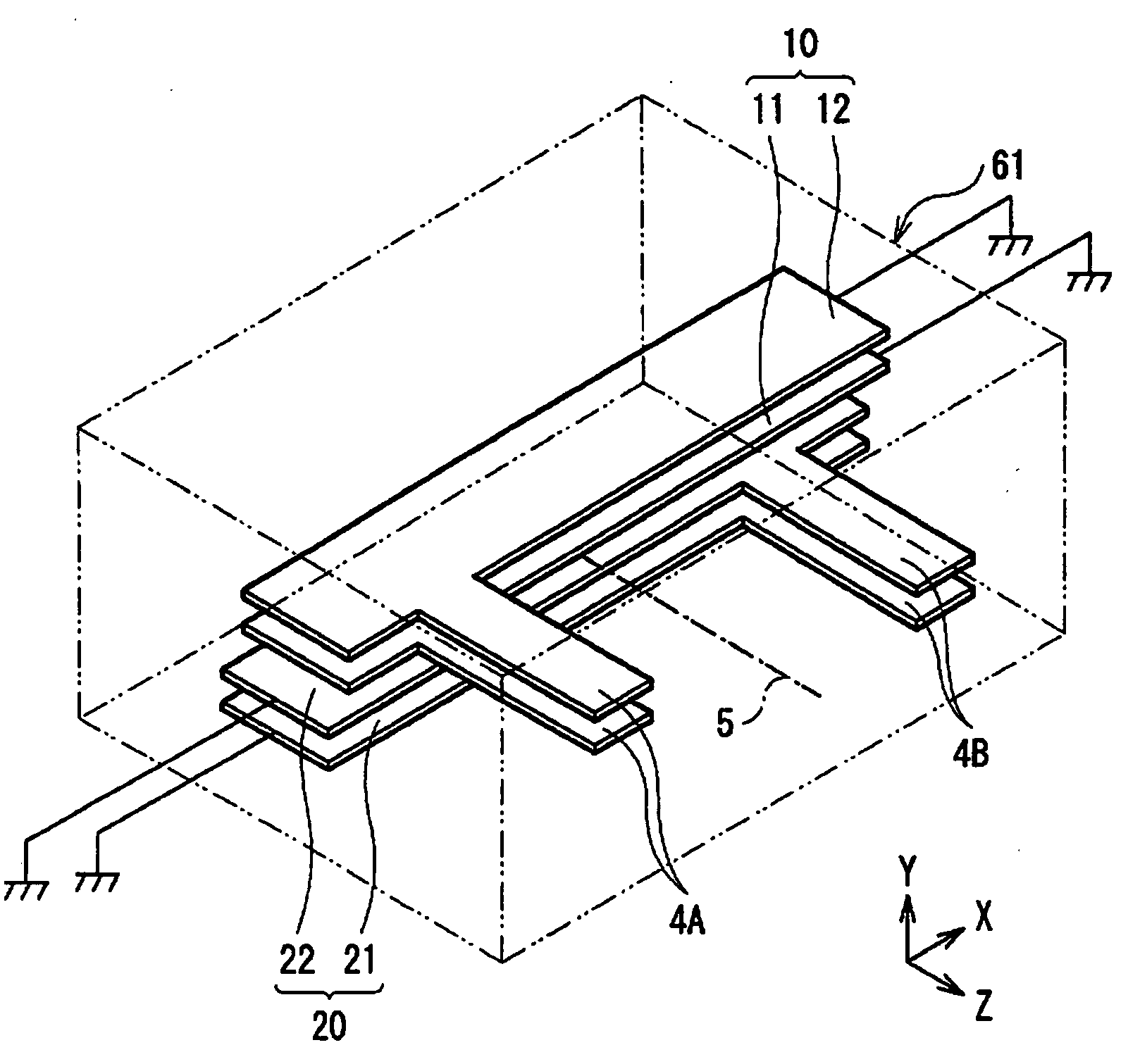
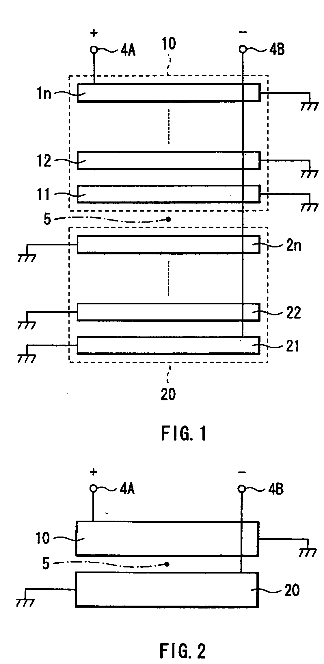
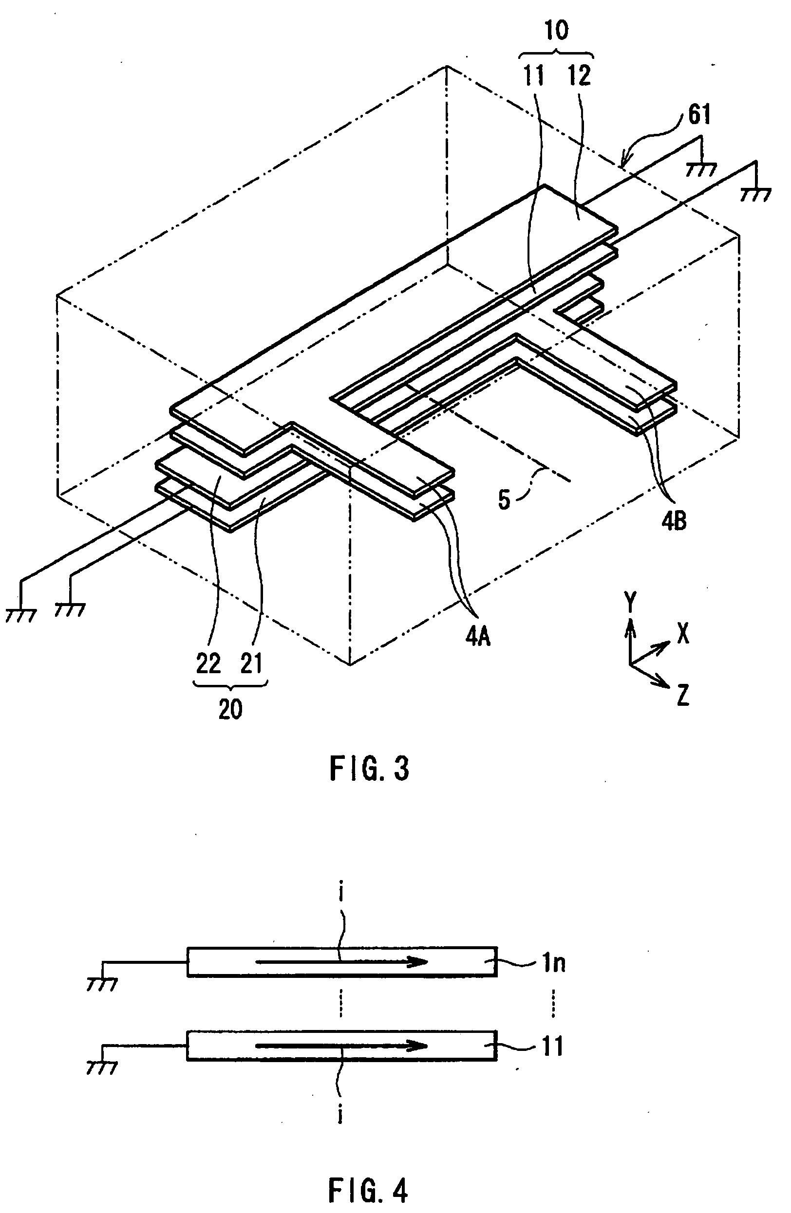
[0056]First, a stacked resonator according to a first preferred embodiment of the present invention will be described. FIG. 1 illustrates a basic configuration of the stacked resonator of the present embodiment. FIG. 2 illustrates an equivalent configuration of the stacked resonator in the present embodiment. This stacked resonator can be used as a component constituting, for example, an antenna or a filter. This stacked resonator has a pair of quarter-wave resonators 10 and 20 which are interdigital-coupled to each other, and a pair of balanced terminals 4A and 4B which are connected to the resonators 10 and 20, respectively.

[0057]One quarter-wave resonator 10 is constructed of a plurality of conductor lines 11, 12, . . . 1n which are stacked and arranged so as to establish a comb-line coupling. The plurality of conductor lines 11, 12, . . . 1n are vertically adjacent to each other, and stacked and arranged with predetermined spaced intervals, and they are also arranged so that the...

second preferred embodiment

[0087]A stacked resonator according to a second preferred embodiment of the present invention will next be described. The same reference numerals have been used as in the above-mentioned first preferred embodiment for substantially identical components, with the description thereof omitted.

[0088]FIG. 12 illustrates a basic configuration of the stacked resonator of the second preferred embodiment. FIG. 13 illustrates an equivalent configuration of the stacked resonator in the second preferred embodiment. The stacked resonator according to the first preferred embodiment is provided with a set of the pair of quarter-wave resonators 10 and 20, whereas the stacked resonator according to the second preferred embodiment is provided with a plurality of pairs of quarter-wave resonators, which are configured in a multistage. The configuration example of FIG. 12 is provided with two sets of one pair of quarter-wave resonators 10 and 20, and the other pair of quarter-wave resonators 110 and 120...

third preferred embodiment

[0094]A third preferred embodiment of the present invention will be described below. The present embodiment describes a filter using the stacked resonator according to the first preferred embodiment mentioned above. The same reference numerals have been used as in the above-mentioned first preferred embodiment for substantially identical components, with the description thereof omitted.

[0095]FIG. 16 illustrates a basic configuration of the filter in the third preferred embodiment. FIG. 15 illustrates an equivalent configuration of the filter in the third preferred embodiment. The present embodiment describes taking as example a filter of unbalanced input / balanced output type or balanced input / unbalanced output type, having a balanced terminal only on either an input end side or an output end side, and having an unbalanced terminal on the other. This filter is provided with a first resonator 1, a second resonator 2, an unbalanced terminal 3 connected to the first resonator 1, and a p...


PUM


Abstract

A stacked resonator and a filter are provided which are capable of achieving miniaturization and minimum loss, and also capable of transmitting a balanced signal with superior balance characteristics. There are provided a pair of quarter-wave resonators which are interdigital-coupled to each other. One quarter-wave resonator is constructed of a plurality of conductor lines which are stacked and arranged so as to establish a comb-line coupling. By the stacked arrangement so as to establish a comb-line coupling of the plurality of conductor lines, the conductor thickness of this quarter-wave resonator can be increased virtually thereby reducing the conductor loss. Similarly, the other quarter-wave resonator is constructed of a plurality of conductor lines stacked and arranged so as to establish a comb-line coupling, and hence the conductor thickness of this quarter-wave resonator can be increased virtually thereby reducing the conductor loss.

Description

BACKGROUND OF THE INVENTION[0001]1. Field of the Invention[0002]The present invention relates to a stacked resonator with a plurality of conductors stacking one upon another, and a filter constructed by using the stacked resonator.[0003]2. Description of the Related Art[0004]For example, demanding requirements of miniaturization and minimum loss are placed on filters used in radio communication equipments such as cellular phones. Consequently, the same is true for resonators constituting the filters. As a filter having a balanced terminal, there is known for example a band pass filter of unbalanced input / balanced output type. As such a filter, there is one using a balun. The balun is used to perform mutual conversion between an unbalanced signal and a balanced signal. In a line for transmitting an unbalanced signal, a signal is transmitted by the potential of a signal line with respect to a ground potential. In a line for transmitting a balanced signal, a signal is transmitted by th...

Claims


Application Information

Patent Timeline
Patent Type & Authority Applications(United States)
IPC IPC(8): H01P1/203
CPCH01P1/20345
Inventor FUKUNAGA, TATSUYA
Owner TDK CORPARATION
Why Eureka
Try Eureka