Capture rcdt and sntt sas speed negotiation decodes in a network diagnostic component

a network diagnostic and sas technology, applied in the field of capture rcdt and sntt sas speed negotiation decoding in the network diagnostic component, can solve the problems of increased size, speed and complexity, difficult diagnosis and resolution, and increased communication bandwidth

Active Publication Date: 2007-09-06
VIAVI SOLUTIONS INC
View PDF50 Cites 8 Cited by
  • Summary
  • Abstract
  • Description
  • Claims
  • Application Information

AI Technical Summary

Benefits of technology

[0007]Embodiments disclosed herein relate to a network diagnostic device or component that is placed in-line between two nodes in a network to capture the timing value of a portion of a speed negotiation signal. For example, the network diagnostic component receives a speed negotiation signal from a first node for communication with a second node. The speed negotiation signal may be received by a receive module. The speed negotiation signal includes at least a first portion that comprises one or more data units.

Problems solved by technology

Computer and data communications networks continue to proliferate due to declining costs, increasing performance of computer and networking equipment, and increasing demand for communication bandwidth.
As communication networks have increased in size, speed and complexity however, they have become increasingly likely to develop a variety of problems that, in practice, have proven difficult to diagnose and resolve.
The problems generally experienced in network communications can take a variety of forms and may occur as a result of a variety of different circumstances.
Examples of circumstances, conditions and events that may give rise to network communication problems include the transmission of unnecessarily small frames of information, inefficient or incorrect routing of information, improper network configuration and superfluous network traffic, to name just a few.
Such problems are aggravated by the fact that networks are continually changing and evolving due to growth, reconfiguration and introduction of new network topologies and protocols.

Method used


Image

  • Capture rcdt and sntt sas speed negotiation decodes in a network diagnostic component
  • Capture rcdt and sntt sas speed negotiation decodes in a network diagnostic component
  • Capture rcdt and sntt sas speed negotiation decodes in a network diagnostic component

Examples


Embodiment Construction

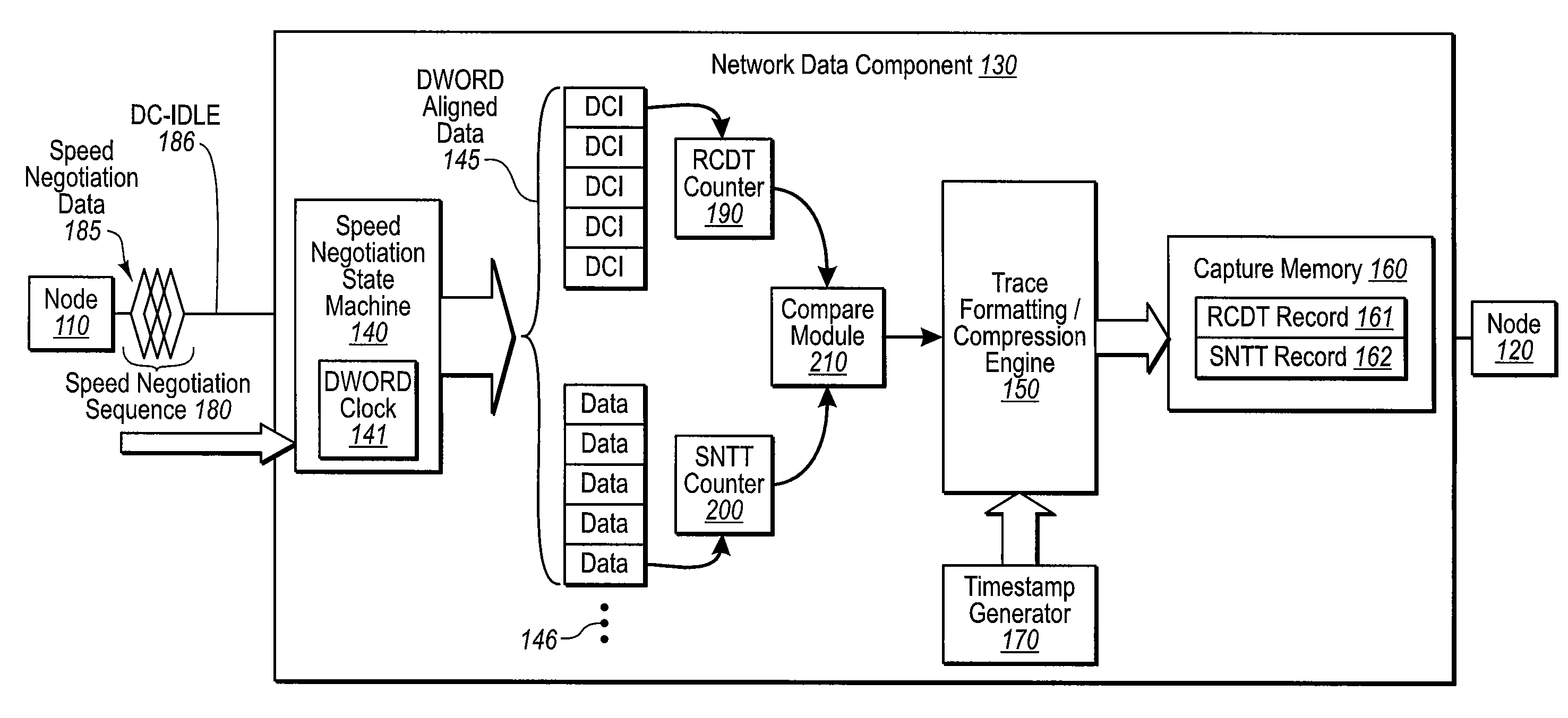
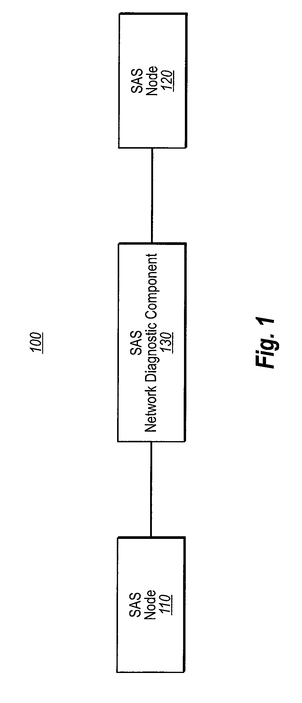
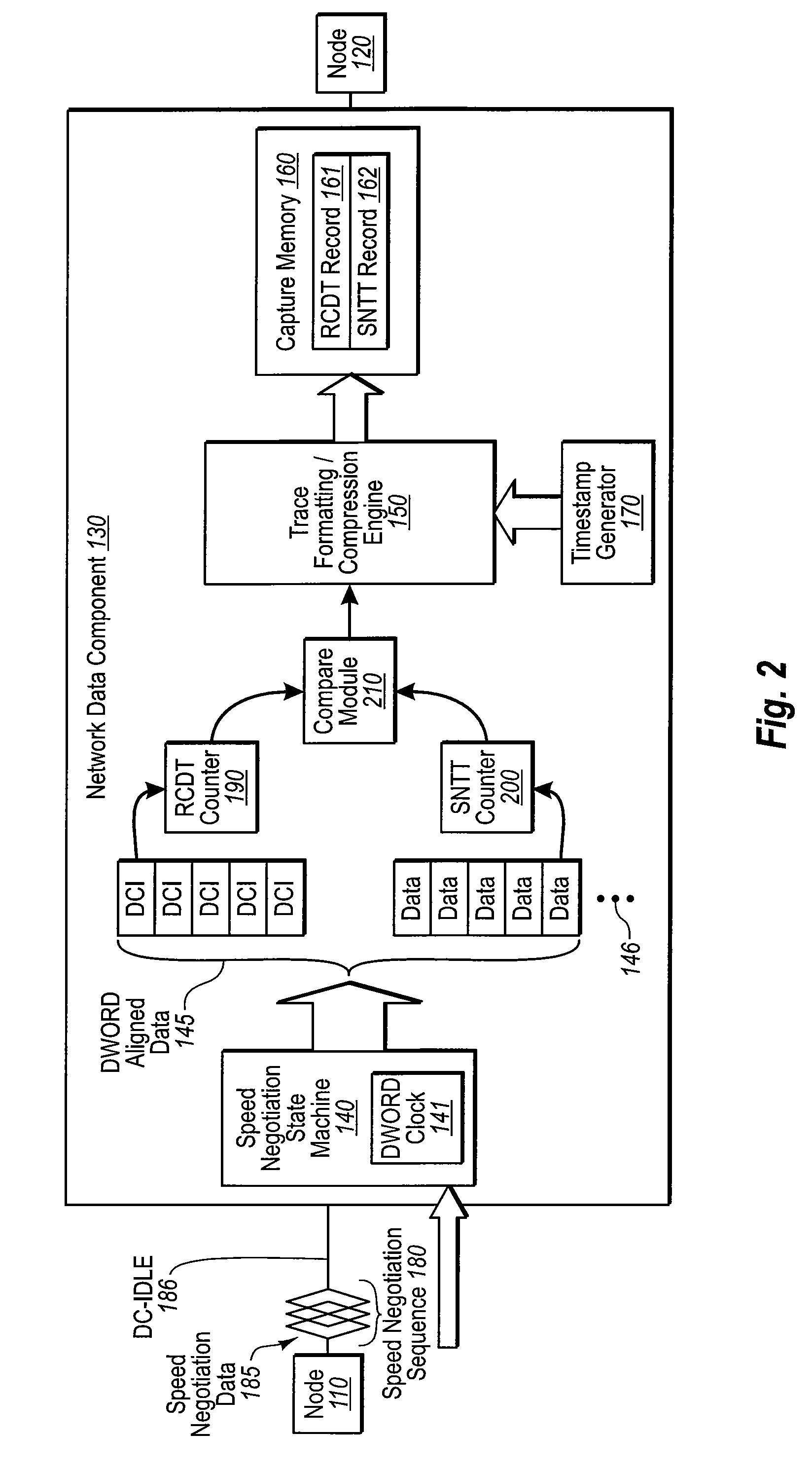
[0016]The embodiments disclosed herein relate to a network diagnostic component or device that is placed in-line between a first and second node. The diagnostic component or device is used to capture the timing value of a component of a speed negotiation signal. For example, the first node may communicate with the second node using a speed negotiation signal that includes a first component comprising one or more data units. In some embodiments, the speed negotiation signal may be of the SAS protocol. The network diagnostic component may receive the speed negotiation data and measure the duration of the data units of the first component. The network diagnostic component may then compare the measured value with a desired duration value and generate a record of the comparison. In some embodiments a timestamp is affixed to the generated record. In other embodiments, the generated record is displayed on a display device.

[0017]The embodiments disclosed herein may be practiced in networkin...


PUM


Abstract

Systems and methods for a network diagnostic device or component that is placed in-line between two nodes in a network to capture the value of a component of a speed negotiation signal. The network diagnostic component receives a speed negotiation signal from a first node for communication with a second node. The speed negotiation signal may be received by a receive module. The speed negotiation signal includes one at least a first portion that comprises one or more data units. The network diagnostic component measures the duration of the data units of the first component of the speed negotiation data. This measurement may be performed by a measurement module. The network diagnostic component compares the measured duration with a desired duration. The comparison may be performed by a measurement module. A record of whether the measured duration compares with the desired duration is then generated by a generation module.

Description

CROSS-REFERENCE TO RELATED APPLICATIONS[0001]This application claims the benefit of U.S. Provisional Application No. 60 / 779,040, filed Mar. 3, 2006, which is incorporated herein by reference in its entirety.BACKGROUND[0002]Computer and data communications networks continue to proliferate due to declining costs, increasing performance of computer and networking equipment, and increasing demand for communication bandwidth. Communications networks—including wide area networks (“WANs”), local area networks (“LANs”), metropolitan area networks (“MANs”), and storage area networks (“SANS”)—allow increased productivity and use of distributed computers or stations through the sharing of resources, the transfer of voice and data, and the processing of voice, data and related information at the most efficient locations. Moreover, as organizations have recognized the economic benefits of using communications networks, network applications such as electronic mail, voice and data transfer, host a...

Claims


Application Information

Patent Timeline
Patent Type & Authority Applications(United States)
IPC IPC(8): H04J1/16
CPCH04L43/067H04L43/16H04L43/0852
Inventor VEDANABHATLA, KIRANMAIHIBBERT, GEOFFREY T.KLOTZ, STEVEN R.
Owner VIAVI SOLUTIONS INC
Why Eureka
Try Eureka