Remote terminal unit and monitoring, protection and control of power systems

a remote terminal and power system technology, applied in the direction of time-division multiplex, electrical equipment, circuit arrangements, etc., can solve the problems of increasing the stability limit of the operation of the power system, the transmission bottleneck and electromechanical oscillation of parts of the electric power system, and the reduction of the operational margin of many power systems world wid

Inactive Publication Date: 2007-09-06
ABB TECH AG
View PDF10 Cites 63 Cited by
  • Summary
  • Abstract
  • Description
  • Claims
  • Application Information

AI Technical Summary

Benefits of technology

[0015] In an exemplary variant of the disclosure, the phasor measurement facility can be arranged in one sub-RTU or several sub-RTUs distributed over the substation and connected to a single core-RTU comprising the communication gateway. The hard-wired connections to the process can thus be shared between the data acquisition means for network data destined to slow management purposes and phasor data evaluated by Wide-Area monitoring, control and / or protection applications. Furthermore, the RTUs can be independent of the Local Operating Network (LON) for Substation Automation communication. Thus, the instantaneous protection services provided by the bay units or protection relays are not impeded by phasor data being transferred over the LON and possibly conflicting with the time-critical commands for bay level protection of the individual substations of the electric power system.
[0016] In an advantageous exemplary embodiment, the phasor data is communicated to the Network Control Centre (NCC) via the communication gateway of the RTU and the dedicated communication link between the latter and the NCC. Thereby advantage is taken of the fact that the phasor measurement facilities need not be synchronized over a communication link for mutual data exchange, as they obtain the synchronizing signal over an independent channel. In addition, forwarding of time-stamped phasor values in a non-time critical manner to a Wide-Area control centre does not require the provision of a separate upstream communication link.

Problems solved by technology

In the past years, continued load growth without a corresponding increase in transmission resources has resulted in reduced operational margins for many power systems world wide, and has led to operation of power systems ever closer to their stability limits.
Likewise, load transmission and wheeling of power from distant generators to local load consumers has become common practice, and led to substantially increased amounts of power being transmitted through the existing networks, occasionally even causing transmission bottlenecks and electromechanical oscillations of parts of the electric power systems.

Method used


Image

  • Remote terminal unit and monitoring, protection and control of power systems
  • Remote terminal unit and monitoring, protection and control of power systems
  • Remote terminal unit and monitoring, protection and control of power systems

Examples


Embodiment Construction

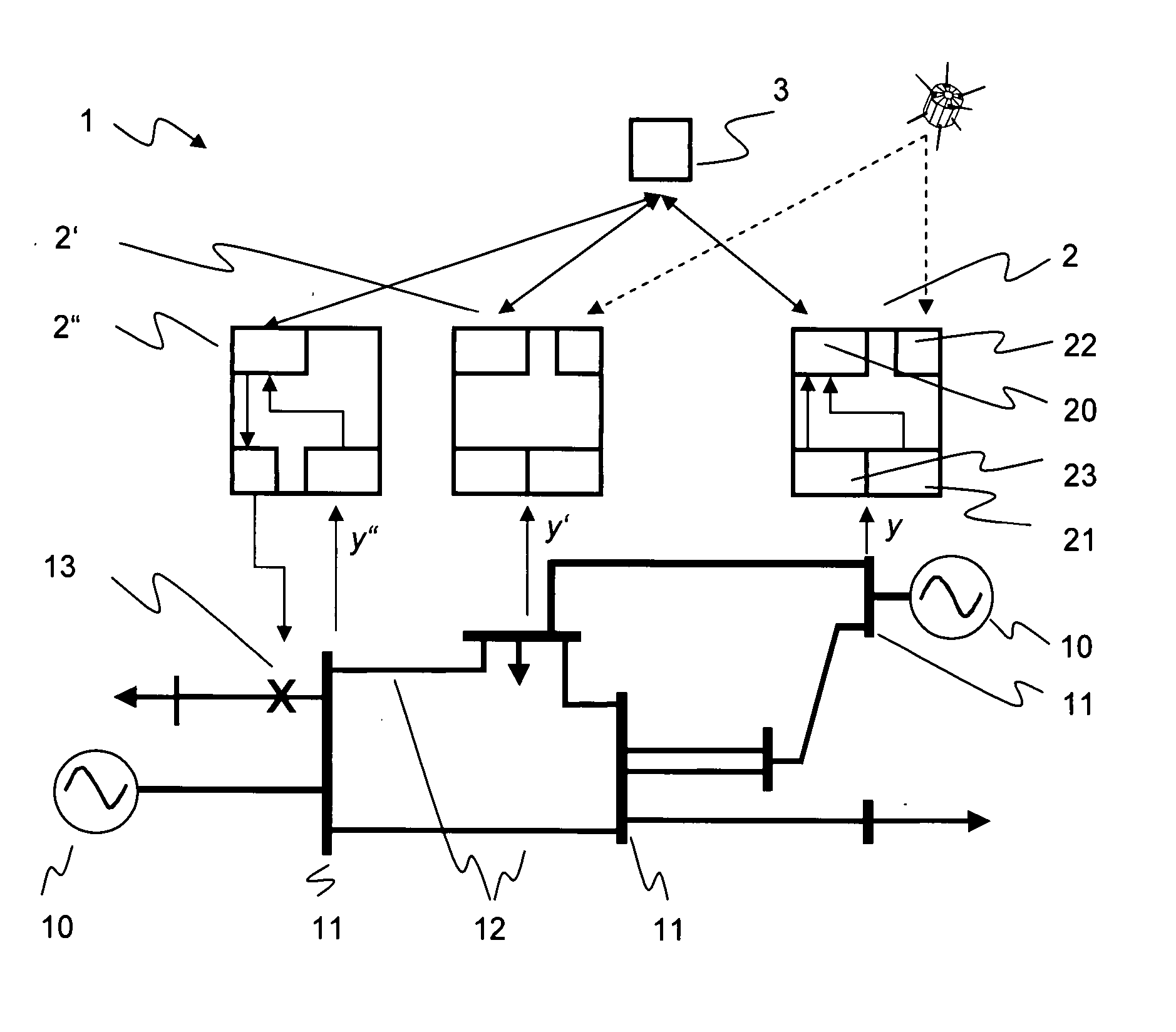
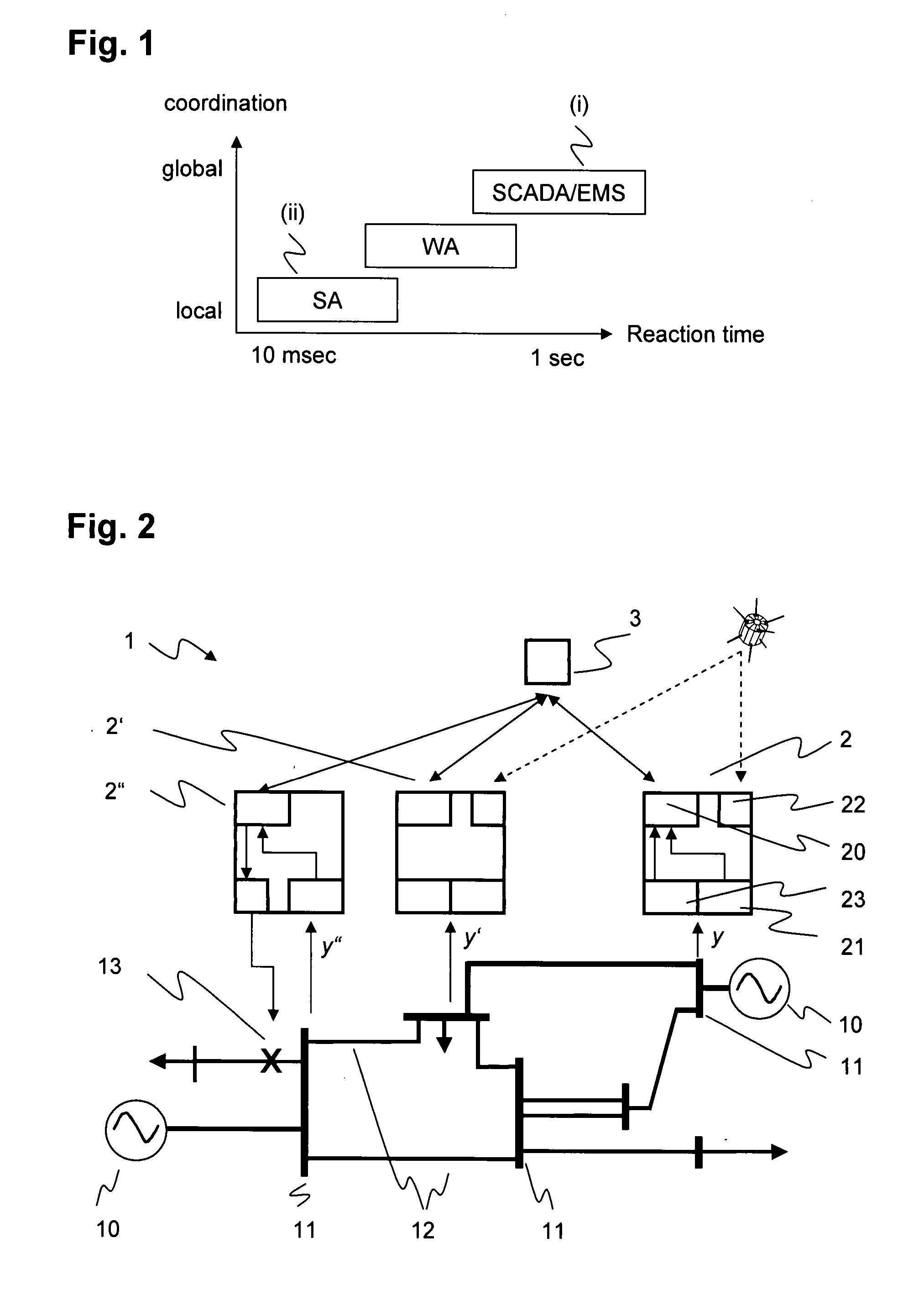
[0022]FIG. 2 shows an overview of an exemplary power system 1 with generators 10 and substations represented each by a busbar 11 and interconnected by transmission lines 12. From a topological point of view, the busbars 11 in the substations form the nodes of the electrical power transmission network of the power system 1. Remote Terminal Units (RTU) 2 can be assigned to the various substations. Exemplary RTU 2 comprises first data acquisition means 21 for measuring network data in the form of root mean square (RMS) values of system quantities yi such as voltage or current at a particular point of the corresponding substation. It further comprises a communication gateway 20 for forwarding the measured network data to a Network Control Centre (NCC) 3 of a Supervisory Control And Data Acquisition / Energy Management System (SCADA / EMS) or other control and protection system. At least the exemplary RTU 2 can be equipped with synchronization means 22 that provides time stamps according to ...


PUM


Abstract

The disclosure relates to phasor-based monitoring, protection and control applications in electric power systems supervised and/or managed by a Supervisory Control And Data Acquisition/Energy Management System (SCADA/EMS). In order to enable the applications without incurring heavy infrastructural investments, a phasor measurement facility is integrated into a Remote Terminal Unit (RTU) that is part of the SCADA/EMS system and comprises Input/Output (I/O) interfaces hard-wired to a substation of an electric power system. By taking advantage of the fact that RTUs as indispensable building blocks for any SCADA/EMS are part of every substation of the power system, no extra housing, cabling and EMC shielding for the additional functionality needs to be provided.

Description

RELATED APPLICATIONS [0001] This application claims priority under 35 U.S.C. §119 to European Application 06405089.1 filed in the European Patent Office on 2 Mar. 2006, the entire contents of which are hereby incorporated by reference in their entireties. FIELD [0002] The disclosure relates to the field of Wide-Area monitoring, protection and control of electric power systems. BACKGROUND INFORMATION [0003] An electric power system comprises a power transmission and / or distribution network interconnecting geographically separated regions, and a plurality of substations at the nodes of the power network. The substations include equipment for transforming voltages and for switching connections between individual lines of the power network. Power generation and load flow to consumers is managed by a central Energy Management System (EMS) and / or supervised by a Supervisory Control And Data Acquisition (SCADA) system. SCADA / EMS systems have a centralized structure with a Network Control C...

Claims


Application Information

Patent Timeline
Patent Type & Authority Applications(United States)
IPC IPC(8): H04J3/06
CPCH02J13/0062Y02B90/2638Y02E60/74Y04S10/30Y04S40/124H02J13/00002H02J13/00016H02J13/00034Y02B90/20Y02E60/00
Inventor BERTSCH, JOACHIMSURANYI, ANDREASJAGGY, ENGELBERT
Owner ABB TECH AG
Why Eureka
Try Eureka