
Image encoding apparatus and method

a technology of image data and encoder, applied in the field of image data compressioncoding technique, can solve the problems of lossy process, image and natural image pose many problems, image and lossy process cannot guarantee high image quality for all kinds of images, etc., and achieve the effect of quick generation of encoded data and preventing any sense of discomfor

Inactive Publication Date: 2007-09-06
CANON KK
View PDF18 Cites 29 Cited by
  • Summary
  • Abstract
  • Description
  • Claims
  • Application Information

AI Technical Summary

Benefits of technology

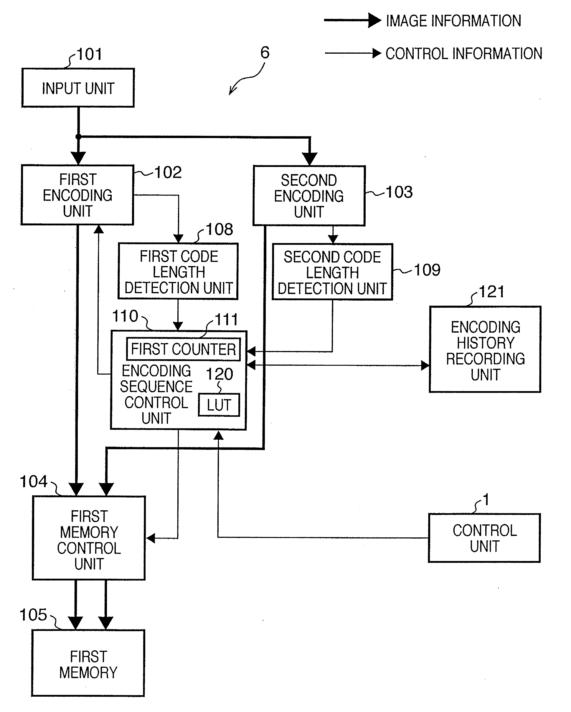
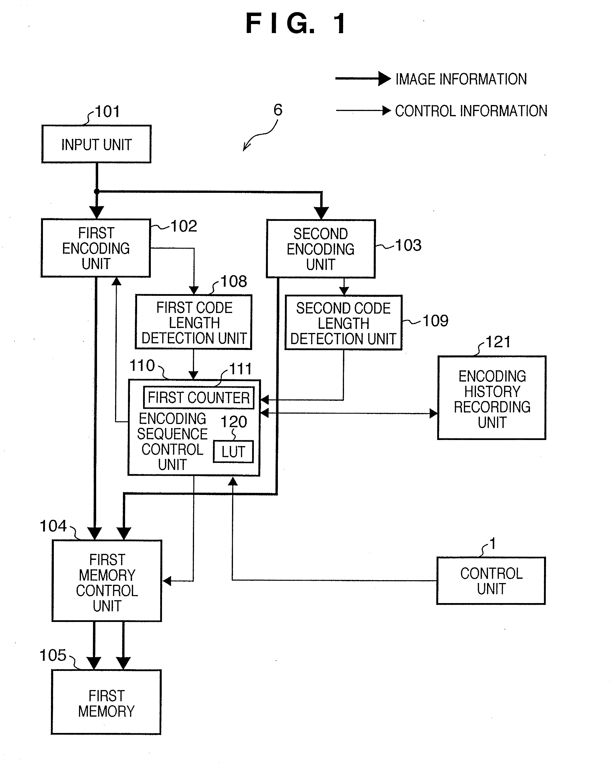
The present invention provides a technique for generating encoded data that contains both lossless encoded data and lossy encoded data, and ensures that the amount of encoded data does not exceed a target. This technique allows for adaptive switching between lossless encoding and lossy encoding based on image attributes without the need for special image area determination techniques. Additionally, the invention allows for quick generation of encoded data with minimal image degradation and ensures that the amount of encoded data does not exceed a target. The invention also includes a history information storage means and a control means for updating the parameters used in the encoding process based on the history information. Overall, the invention provides a more efficient and effective technique for image compression.

Problems solved by technology

However, the lossy process cannot guarantee a high image quality for all kinds of images.
This degrades the image at a high probability.
Especially compression-coding of an image containing both a character / line image and a natural image poses many problems.
This is because raising the quantization step rarely affects the quality of a natural image but makes the edge of a character / line image unclear.
Hence, the process executed by the apparatus inevitably becomes complex, resulting in a high cost.
In lossless encoding, however, the compression ratio is nonadjustable, unlike lossy encoding.
Hence, if the encoded data amount obtained by lossless encoding exceeds the target code amount, it is difficult to take a further measure.
Hence, the image quality of a character / line image area in a document image unavoidably degrades depending on the employed quantization matrix.

Method used


Image

  • Image encoding apparatus and method
  • Image encoding apparatus and method
  • Image encoding apparatus and method

Examples


second embodiment

[0192]In the above-described embodiment, when the encoded data amount (the value of the first counter 111) stored in the first memory 105 has exceeded the target code amount Th, the lossless encoded data amount MLS and lossy encoded data amount MJP in the encoded data are compared. The variables i and j of the next scanning are decided in accordance with the comparison result. In the second embodiment, an example of more accurate decision of variables i and j will be described.

[0193]Prior to the description, assume that when fi,j( ) changes to fi+1,j( ), a statistical decrement R((i,j),(i+1,j)) of the lossy encoded data length with respect to the pixel block is obtained. When fi,j( ) is used, the average lossy encoded data length of the pixel block is defined as C(fi,j( )). The decrement R((i,j),(i+1,j)) at this time is given by

R((i,j), (i+1,j) )=C(fi+1,j( )) / C(fi,j( ))

[0194]Similarly, assume that when fi,j( ) changes to fi,j+1( ) a statistical decrement R((i,j), (i,j+1) ) of the lo...

third embodiment

[0224]In the second embodiment, the predicted encoded data amounts Mtotal′, Mtotal″, and Mtotal′″ of one page are obtained, and re-encoding is executed by using encoding parameters corresponding to the data amount closest to the target code amount. In the third embodiment, an example will be described in which the encoding parameters are decided depending on the encoding target image. The apparatus arrangement is the same as in the first embodiment.

[0225]The structure of data stored in an encoding history recording unit 121 is the same as in the second embodiment. The predicted code amounts and predicted selection signals of lossy encoded data amount Ly are obtained in correspondence with all encoding parameters i and j.

[0226]FIGS. 25 to 27 show the boundary lines of boundary conditions fi,j( ) which are specified by the variables i (also serving as a variable to decide a quantization matrix Qi) and j stored in an LUT 120. FIGS. 25 to 27 illustrate an example of nine boundary lines ...

fourth embodiment

[0259]The fourth embodiment will be described. The fourth embodiment further advances the third embodiment. Details will be described below.

[0260]In the third embodiment, the coefficient β of inequality (4)

Mpz≦(MLSz+MJPz)×Nmax / k+β

is a positive value.

[0261]As can easily be seen from inequality (4), the larger the coefficient β is, the higher the probability to satisfy the condition is. Assume that the priority order shown in FIG. 25 is decided. If the value β is sufficiently large, the condition is immediately satisfied by the priority order P1, and re-scanning / re-encoding starts by using the encoding parameters i=1 and j=0.

[0262]In actual image data encoding, if the code amount decreases to a target code amount Th or less when the encoding parameters corresponding to a priority order P4 are used, scanning / encoding is executed five times in total on the basis of P0, P1, P2, P3, and P4. That is, when the coefficient β is set to a large value, it is possible to generate encoded data to...


PUM


Abstract

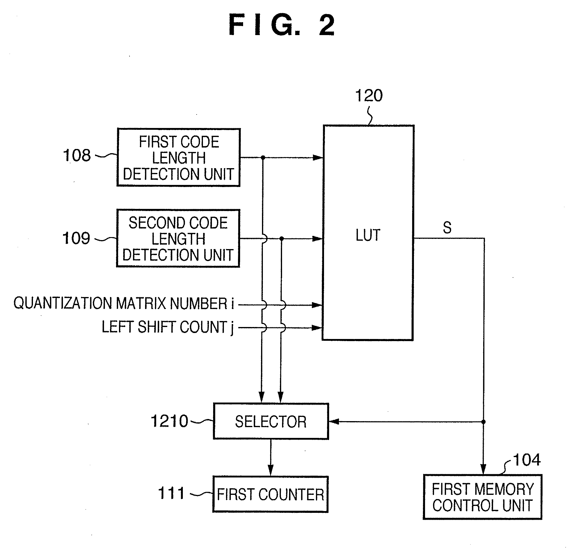
This invention is to generate encoded data within a target amount. A first encoding unit generates lossy encoded data of each pixel block by using a quantization matrix Qi specified by a parameter i. A second encoding unit generates lossless encoded data of each pixel block. Let Lx be the lossless encoded data length, and Ly be the lossy encoded data length. A control unit determines, using a nonlinear boundary function fi,j( ) specified by the parameters i and j, whether condition: Ly<fi,j(Lx) is satisfied and stores the determination result as history information in a history memory unit. One of the two encoded data is stored in a memory based on the determination result. If the encoded data amount stored in the memory has exceeded the target amount, the control unit updates at least one of the encoding parameters i and j on the basis of the history information.

Description

BACKGROUND OF THE INVENTION[0001]1. Field of the Invention[0002]The present invention relates to an image data compression-coding technique.[0003]2. Description of the Related Art[0004]To compress a still image, conventionally, JPEG schemes using discrete cosine transform or schemes using Wavelet transform are often used. An encoding scheme of this type is a variable length encoding scheme which changes the code amount depending on the encoding target image.[0005]The JPEG scheme as an international standard can define only one set of quantization matrices for an image of one page. Hence, when a document is scanned, and its image data is encoded, the resultant encoded data amount may exceed the expected target code amount.[0006]If the code amount has exceeded the expected amount, commonly, the quantization matrices are changed to change the compression ratio, and the document is re-read. There is also a method of estimating the code amount by prescanning and resetting quantization pa...

Claims


Application Information

Patent Timeline
Patent Type & Authority Applications(United States)
IPC IPC(8): G06K9/36
CPCH04N19/176H04N19/172H04N19/196H04N19/423H04N19/12H04N19/124H04N19/152H04N19/60
Inventor TAMURA, HIROKAZUITO, NAOKI
Owner CANON KK
Learn More