Thrust roller bearing

a technology of roller bearings and bearings, which is applied in the direction of bearings, shafts and bearings, rotary machine parts, etc., can solve the problems of not being retained by the rollers coming, narrow retaining portions of the roller at each bent portion, and difficult to form precisely, so as to improve the lubrication and cage strength of the bearings, and low cost

Active Publication Date: 2007-09-06
JTEKT CORP
View PDF16 Cites 10 Cited by
  • Summary
  • Abstract
  • Description
  • Claims
  • Application Information

AI Technical Summary

Benefits of technology

[0010]The invention has been conceived to solve those problems, and has an object to provide a thrust roller bearing, which uses rollers of a shor...

Problems solved by technology

As a result, the roller retaining portions disposed at each bent portion become narrow and hard to form precisely.
As a result, when the roller is inclined to move so far that its end surface is supported by the inner surface of the rib, the roller is not caught on the roller end surfac...

Method used


Image

  • Thrust roller bearing
  • Thrust roller bearing
  • Thrust roller bearing

Examples


embodiment 1

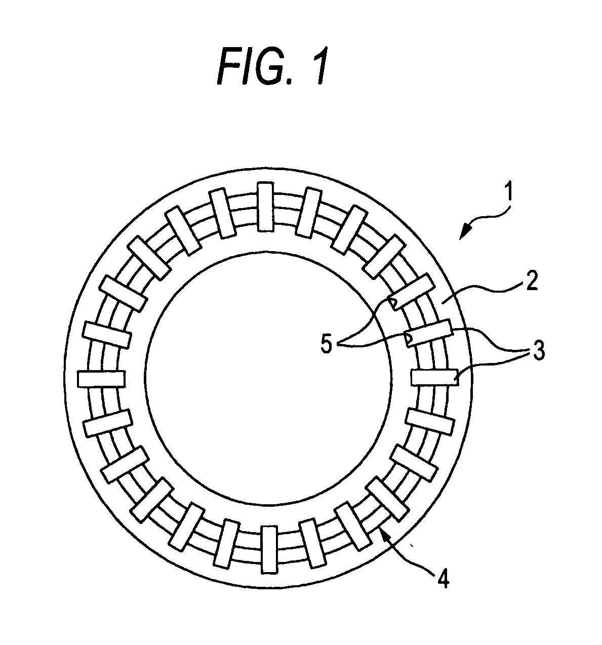
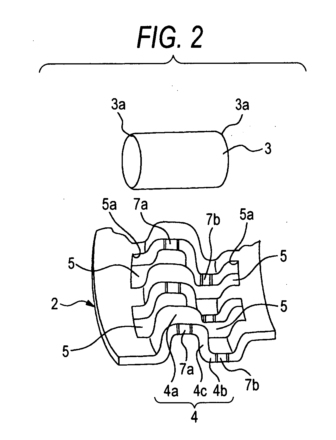
[0032]FIG. 1 is a top plan view showing a thrust roller bearing according to Embodiment 1 of the invention; FIG. 2 is a perspective view showing the pocket periphery of the same thrust roller bearing in an enlarged scale; FIG. 3 is a top plan view showing the pocket periphery of the same thrust roller bearing in an enlarged scale; FIG. 4 is a sectional view along line IV-IV of FIG. 3; and FIG. 5A to FIG. 5C are sectional views showing the various mounted states of the rollers in the cage of the same thrust roller bearing.

[0033]In the drawings, the thrust roller bearing 1 according to Embodiment 1 of the invention is structured to include a thrust roller bearing 1, a cage 2 and a plurality of rollers 3.

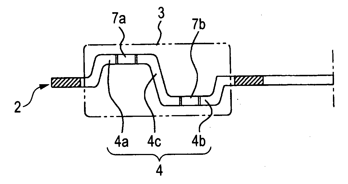
[0034]The cage 2 is made of one annular plate and drawn to have a crank-shaped axially bent portion 4 at its radially intermediate area.

[0035]Each of the crank-shaped bent portions 4 is composed of radially outer and inner side extended portions 4a and 4b, which are so extended in one ...

embodiment 2

[0057]FIG. 6 is a top plan view showing a portion of the pocket periphery of a thrust roller bearing of Embodiment 2 of the invention in an enlarged scale.

[0058]In FIG. 6, the structures similar to those of Embodiment 1 are omitted on their overlapped description by designating them by the common reference numerals.

[0059]In Embodiment 2, as shown in FIG. 6, of the inner wall surfaces of the pocket 5, the individual wall surface portions on the radially outer side and on the radially inner side are provided with protrusions 8 and 9 protruded into the pocket 5, so that the axially inner and outer end surfaces of the roller 3 are received by the protrusions 8 and 9 before the chamfered portions 3a of the roller 3 abut against the inner corners 5a of the pocket 5.

[0060]In this case, the protrusions 8 and 9 are disposed at positions where they abut against the center portions of the outer end surface and the inner end surface of the roller 3 in the axial direction thereby to support the ...


PUM


Abstract

A cage of a thrust roller bearing includes: a pair of crank-shaped bent portions arranged in a circumferential direction of the cage; a pair of inner wall surfaces arranged in a radial direction of the cage; and a pocket for housing a roller defined by the pair of bent portions and the pair of inner wall surfaces and formed by punching the cage. Radially inner one of the inner wall surfaces is formed as a guiding surface for guiding a substantial roller PCD position of an end surface of the roller. Each of the pair of bent portions includes a first extended portion extending in one of cage thickness directions and a second extended portion extending in the other cage thickness direction. A roller retaining pawl for retaining the roller is provided at each of the first and second extended portions so as to protrude into the pockets.

Description

BACKGROUND OF THE INVENTION[0001]The present invention relates to a thrust roller bearing, and prevents thrust needle rollers from coming out of a cage.[0002]In the thrust roller bearing of the related art having rollers and a cage for holding the rollers, the cage is generally made of a press molding of a thin steel plate, and has ribs at the radially outer side end portion and at the radially inner side end portion. Moreover, pockets for mounting a plurality of rollers of the cage are so formed by a punching work and have a structure in which bent portions positioned across the individual PCD (pitch circle diameter) positions of the rollers in the axial direction are formed at two radial end portions and at the central portions of the individual pockets. The individual rollers are prevented (as referred to Patent Document 1, for example) from coming out in the axial direction of the cage (in the vertical direction) by the roller retaining portions formed at the bent portions in th...

Claims


Application Information

Patent Timeline
IPC IPC(8): F16C33/46
CPCF16C19/30F16C33/543F16C33/4682F16C2300/02
Inventor KOTANI, KAZUYUKINAKASHIMA, YOSHIHITO
Owner JTEKT CORP
Why Eureka
Try Eureka