Split nut with magnetic coupling

Inactive Publication Date: 2007-09-06
CASPI RONI
View PDF16 Cites 604 Cited by
  • Summary
  • Abstract
  • Description
  • Claims
  • Application Information

AI Technical Summary

Benefits of technology

[0004] A split nut has two halves securely fastened to one another by magnets. The magnets may be attached to the nut or the nut itself can be magnetized. The magnets secure the two halves together so that the threads of each half are in alignment and the nut may be moved along a threaded shaft. The nut may be attached to a threaded shaft anywhere along the le

Problems solved by technology

Sometimes this process is not possible.
The shaft may run between two pieces, resulting in no available end for the placement of a nut.
Split nuts using thin flexible hinges suffer from several problems.
Repeated use of the nut will cause metal fatigue in the hinge and eventual breakage.
Also, during transportation or use, a hinge may easily become bent or twisted preventing

Method used


Image

  • Split nut with magnetic coupling
  • Split nut with magnetic coupling
  • Split nut with magnetic coupling

Examples


Example

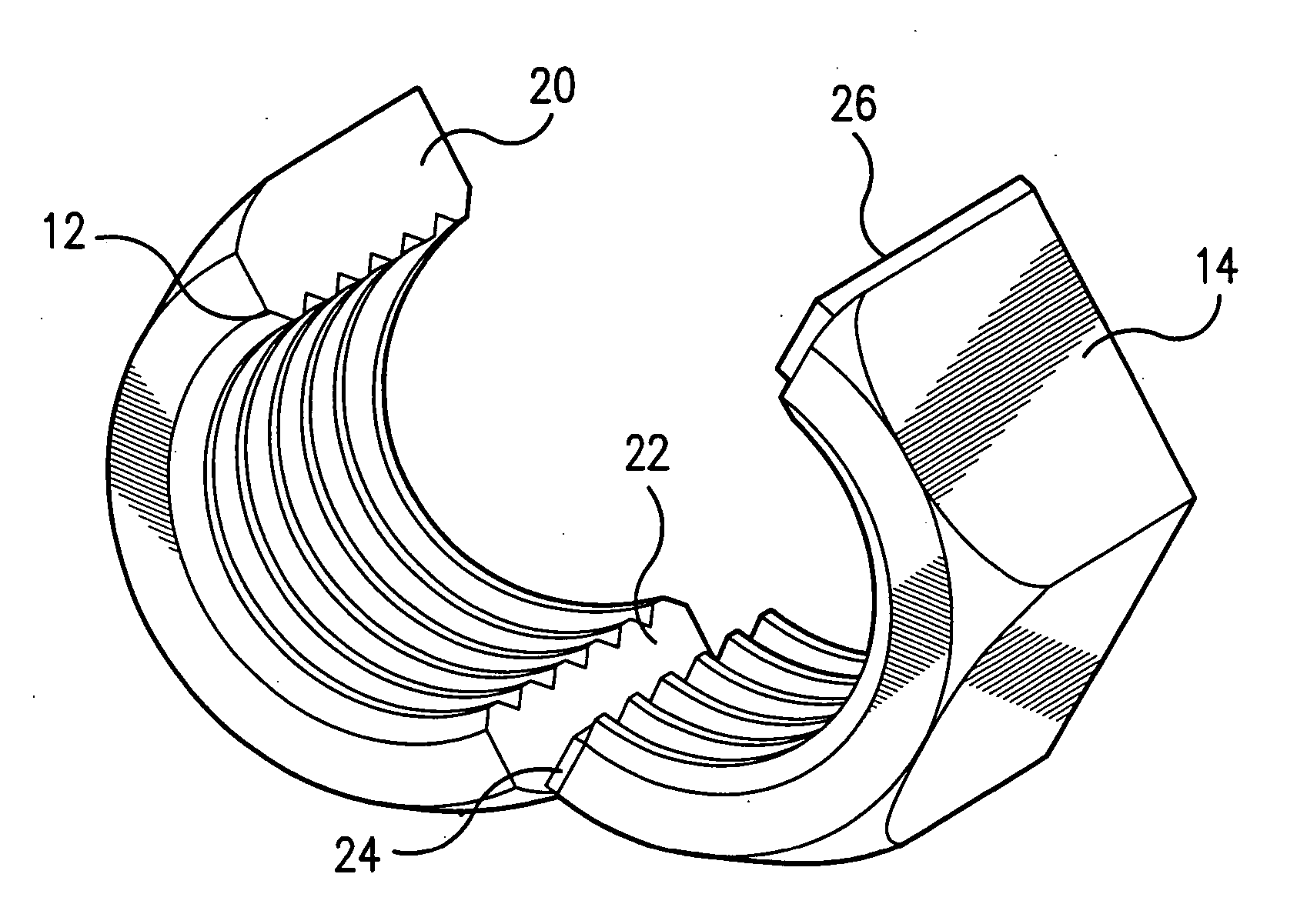
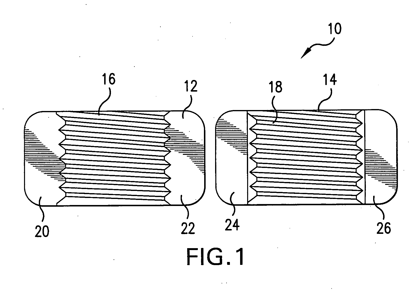
[0009] In FIG. 1, the split nut 10 is seen as having a first half 12 and second half 14. The nut maybe made of any material, such as steel or plastic. The first half has end faces 20, 22 and an inner surface with threads 16. The second half 14 has end faces 24, 26, each provided with a magnet. The magnets are secured to the end face in any conventional manner, such as with adhesive. The inner surface of the second half 14 has threads 18. The threads may be any type and chosen based on the application of the nut.

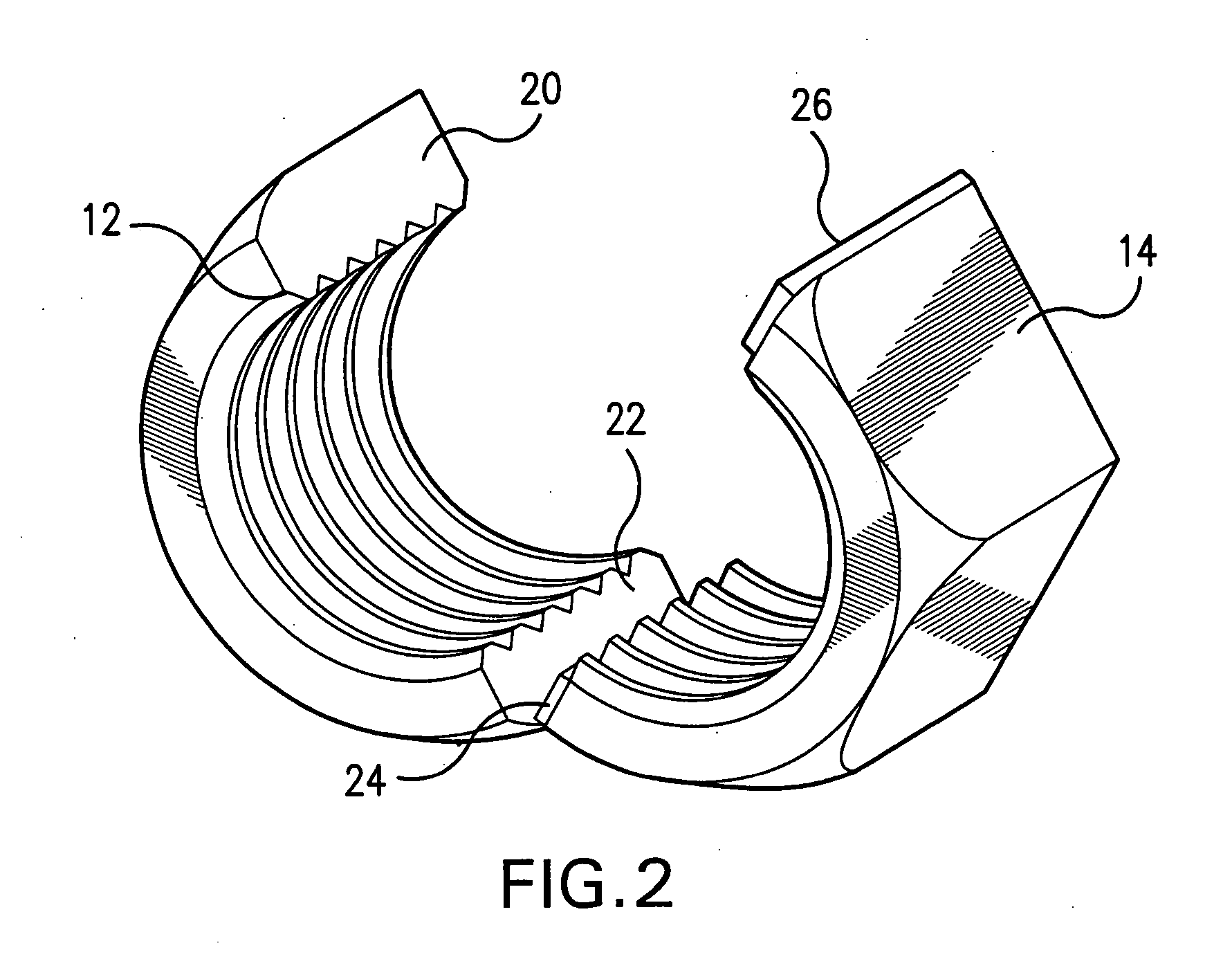
[0010]FIG. 2 shows the two halves with the first magnet 24 in alignment with the end face 22 and the second magnet 26 still having to be brought into contact with the end face 20. With the halves being separable but easily joined, the nut can be placed about a threaded shaft without having to start the nut at the end of the shaft and rotating it to its desired position. The nut halves placed about a bolt is readily seen in FIG. 3. In place of the magnet, the region about the...


PUM


Abstract

A split nut has two halves securely fastened to one another by magnets. The magnets may be attached to the nut or the nut itself can be magnetized. The magnets secure the two halves together so that the threads of each half are in alignment and the nut may be moved along a threaded shaft. The nut may be attached to a threaded shaft anywhere along the length of the shaft. The nut has the ability to realign or reform a damaged portion of the threaded shaft. The nut can also be used for tightening, in the manner of a conventional nut. Moreover, the nut can be used for extracting by pushing, as for example in removing steering wheels for a steering column. Also, if provided with a gasket, the nut can stop leaks.

Description

BACKGROUND OF THE INVENTION [0001] Conventionally, nuts are screwed onto threaded shafts at the end of the shaft. Repeated rotation of the nut causes the nut to move along the shaft to its final desired position. Sometimes this process is not possible. The shaft may run between two pieces, resulting in no available end for the placement of a nut. Also, damage to the threads prevents the entry of the nut on the end fo the shaft. [0002] It is often advantageous to be able to place a nut anywhere along the length of a threaded shaft. The prior art discloses split nuts which may be placed about a threaded shaft. One such disclosure is found in U.S. Pat. No. 2,664,023 (Mugford). Mugford discloses a snap-on split nut having two halves connected by a hinge 32. U.S. Pat. No. 4,657,458 (Woller et al.) discloses an anchor nut for a threaded member having two halves connected together by a thin flexible web or hinge 28 enabling the two sections to be moved from an unfolded position to a folded...

Claims


Application Information

Patent Timeline
IPC IPC(8): F16B37/08
CPCF16B2001/0035F16B37/0892F16B2200/83
Inventor CASPI, RONI
Owner CASPI RONI
Why Eureka
Try Eureka