Quick locking connector

A fast, locking technology, applied in mechanical equipment, couplings, etc., can solve the problems of oil and gas leakage, easy oil leakage or gas leakage, low performance of pipe expansion compensation, and achieve the effect of preventing leakage

Active Publication Date: 2014-05-14
NANTONG AMC MACHINERY
View PDF5 Cites 2 Cited by
  • Summary
  • Abstract
  • Description
  • Claims
  • Application Information

AI Technical Summary

Problems solved by technology

[0002] With the development of science and technology, the application of pipeline system is becoming more and more widely. The existing pipeline connection methods generally include clamp connection, ferrule connection, load-bearing connection and welding connection, etc.; ferrule connection requires A certain installation space, the wall thickness of the connecting pipe also needs to reach a certain thickness; the load-bearing connection method, the connecting pipe end must be pre-formed; the welding connection must be welded on site (commonly known as hot fire in engineering installation, hot fire exists safety Hidden dangers, the installation remains unchanged, and it should be avoided as far as possible in the actual installation); the weldability of the pipes is high, residual stress will be generated during the welding process, and a rigid connection will be formed after welding, and the compensation performance for the pipe expansion caused by temperature changes is low. Welding construction space is limited
[0003] When connecting hard tubes and rubber hoses, clamp-type connections are generally used. However, when the clamping position is too short from the end of the hard tube, oil or air leakage is prone to occur; therefore, the operator must adjust the hose insertion The length of the hard tube meets the technical requirements of assembly; when clamping at certain positions, in order to prevent interference with surrounding parts, it is necessary to turn the clamp and adjust the installation angle. However, special tools must be used for disassembly and assembly of the clamp, so whether it is Installation or disassembly is time-consuming and labor-intensive, and oil and gas leak after disconnection, resulting in a poor working environment

Method used


Image

  • Quick locking connector
  • Quick locking connector
  • Quick locking connector

Examples


Embodiment Construction

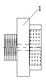
[0022] The quick joint with lock of the present invention comprises: left joint 1, right joint 2;

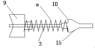
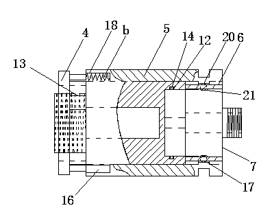
[0023] In order to make the quick joint with lock of the present invention have the functions of convenient connection and disassembly, reliable sealing, and automatic sealing after separation, the quick joint with lock of the present invention is added: left spool assembly 3, joint body 4, joint sleeve 5, single ring Bearing 6, ferrule 7, right spool combination 8, left spool 9, spring a, left thimble 10, support part 11, groove structure 12, circular concave-convex steel pipe with window 13, sealing ring 14, sealing part 15 , spring b, block structure 16, concave structure 17, notch 18, ring member with hole 19, steel ball 20, slot structure 21, right interface 22, right spool 23, spring c, right thimble 24.

[0024] Such as figure 1 ——As shown in 7, the left joint 1 is fixedly connected to the joint body 4, the left valve core assembly 3 is placed in the inner cavity formed ...


PUM


Abstract

The invention discloses a quick locking connector. The quick locking connector is characterized by comprising a left connector, a left valve core assembly, a connector body, a connector sleeve, a single-collar bearing, a clamping sleeve, a right valve core assembly and a right connector, the left connector is fixedly connected with the connector body, the left valve core assembly is placed in an inner cavity formed by connecting the left connector with the connector body, the connector body is sleeved with the connector sleeve, the single-collar bearing is embedded in the connector sleeve, the left end face of the single-collar bearing abuts against the right end face of the connector body, the clamping sleeve is embedded in a chamber formed by connecting the single-collar bearing with the connector body, the right connector is fixedly connected with the clamping sleeve, and the right valve core assembly is arranged in an inner cavity formed by connecting the right connector with the clamping sleeve. The quick locking connector has the functions of being convenient to connect and disconnect, reliable in sealing performance and capable of being closed automatically after being separated.

Description

technical field [0001] The invention relates to a quick connector with a lock, in particular to a quick connector with a lock which is convenient to connect and disassemble, has reliable sealing and can be automatically closed after separation. Background technique [0002] With the development of science and technology, the application of pipeline system is becoming more and more widely. The existing pipeline connection methods generally include clamp connection, ferrule connection, load-bearing connection and welding connection, etc.; ferrule connection requires A certain installation space, the wall thickness of the connecting pipe also needs to reach a certain thickness; the load-bearing connection method must be pre-processed at the connecting pipe end; the welded connection must be welded on site (commonly known as hot fire in engineering installation, hot fire is safe) Hidden dangers, the installation remains unchanged, and should be avoided as far as possible in the ...

Claims


Application Information

Patent Timeline
IPC IPC(8): F16L37/36
CPCF16L37/36
Inventor 戚顺平
Owner NANTONG AMC MACHINERY
Why Eureka
Try Eureka