Joint arrangement

a joint arrangement and joint technology, applied in the field of joint arrangements, can solve the problems of unsatisfactory high friction value and/or noise, slightly skewed installation of the joint arrangement, etc., and achieve the effects of less loss through friction, high precision support, and convenient opening of the hood, trunk lid and/or the rear hatch

Inactive Publication Date: 2007-09-13
STABILUS
View PDF40 Cites 14 Cited by
  • Summary
  • Abstract
  • Description
  • Claims
  • Application Information

AI Technical Summary

Benefits of technology

[0006] In correspondence with the exemplary embodiments of the invention, a joint arrangement, especially a multi-joint hinge, allows a panel of a vehicle to be moved between a closed position and an open position. The joint arrangement or multi-joint hinge has a joint assigned to the vehicle and to the panel. It is advantageous for the joint to have a roller bearing. It is advantageous that the roller bearing minimizes the friction which occurs in the joint even when strong forces are being exerted on the bearing. A joint arrangement of this type can be used to particular advantage for a panel connected to a source of energy, where the source of energy is connected to the vehicle and to the panel in such a way that it minimizes the actuating forces in at least one direction of movement of the panel. Because of the geometries frequently used for panels and the joint arrangements connected to them, the forces acting on the bearings can be very high. When the bearing forces are high, it is possible in particular for undesirably high friction values and / or noise to occur. This is the case especially when conventional joints, especially plain bearings, are used, but excessive friction and noise can be avoided effectively by the use of a roller bearing. A joint arrangement equipped with a roller bearing therefore makes it possible for the panel in question to be opened and closed very easily. Because of the reduced friction values, a high degree of operational reliability is obtained. In addition, the roller bearing can also absorb some of the lever forces acting at a certain angle to the pivot axis without the occurrence of excessive friction values in the bearing. Because of the low friction values, furthermore, the power rating of the source of energy can be made correspondingly lower, as a result of which the overall joint arrangement can be designed with less strength and therefore with a lower weight. The roller bearing of the joint arrangement can also absorb bearing forces which, for example, can be caused by panel misalignment and the manufacturing tolerances of the vehicle body, which can lead to a slightly skewed installation of the joint of the joint arrangement. The roller bearing of the joint arrangement thus makes it possible overall for the panel of the vehicle to which it is attached to be opened and closed more easily and more conveniently.
[0010] In another advantageous exemplary embodiment, the roller bearing has only an outer bearing ring. The rolling elements can therefore be guided inside the outer bearing ring. Advantageously, the hinge pin can take over directly the function of the inner bearing ring of the roller bearing. Therefore, the inner bearing ring can be eliminated. It is advantageous to fabricate the associated hinge pin with sufficiently high surface quality and hardness.
[0012] In another advantageous exemplary embodiment, one of the levers is riveted to the hinge pin. No other component is therefore required to fasten the lever to the hinge pin, as a result of which the number of parts of the joint arrangement can be further reduced.
[0014] In another preferred exemplary embodiment, the joint arrangement is connected to a source of energy. The source of energy can be connected to the vehicle and to the panel by joints. It is also conceivable, however, that the forces could be transmitted from the vehicle to one of the levers of the four-bar joint of the joint arrangement. It is also conceivable that the forces of the source of energy could be transmitted directly between the levers of the joint arrangement. The source of energy can advantageously have a gas spring. The gas spring can store energy which is generated when the panel is opened or closed, so that this energy can be released again during the movement of the panel in the opposite direction. By helping to overcome the force of gravity, the gas spring can make it easier to open the hood, the trunk lid, and / or the rear hatch. Additional functions can also be fulfilled by the source of energy, especially a gas spring, such as a damping function or an arresting function. Because of the highly precise support provided by the roller bearings of the joint arrangement, the forces of the source of energy can be introduced more precisely and with less loss through friction and can therefore be applied with greater efficiency to assist the opening and / or closing of the panel of the vehicle.
[0015] Additional exemplary embodiments of the invention pertain to an assembly for a joint arrangement and to a motor vehicle with an assembly of this type. The assembly has a bearing pin and a roller bearing. The roller bearing has rolling elements, which are guided between an outer bearing ring and the bearing pin. An assembly of this type offers the advantage that it can be easily prefabricated by mounting the rolling elements, for example, on the bearing pin. For this purpose, the rolling elements can also be guided by a cage. Then the bearing ring can be set in place also, so that an assembly is obtained which holds itself together. It is advantageous here that the guide elements of the roller bearing (the bearing consisting here of the bearing pin and the outer bearing ring) which are critical with respect to tolerances already present in the assembly. The inner radius of the bearing ring and the outside surface of the bearing pin should also have an appropriately high degree of surface quality, roundness, tolerance, and hardness. For the rest of the installation process, such as the mounting of the assembly on a lever of the joint arrangement, the outer bearing ring can then be simply pressed into a bore in the lever. It is advantageous that the bore of the associated lever can be produced easily, that is, with comparatively low tolerances. In addition, the inside surface of the bore into which the outer bearing ring of the assembly is pressed can be designed to be relatively soft.

Problems solved by technology

When the bearing forces are high, it is possible in particular for undesirably high friction values and / or noise to occur.
The roller bearing of the joint arrangement can also absorb bearing forces which, for example, can be caused by panel misalignment and the manufacturing tolerances of the vehicle body, which can lead to a slightly skewed installation of the joint of the joint arrangement.

Method used


Image

  • Joint arrangement
  • Joint arrangement
  • Joint arrangement

Examples


Embodiment Construction

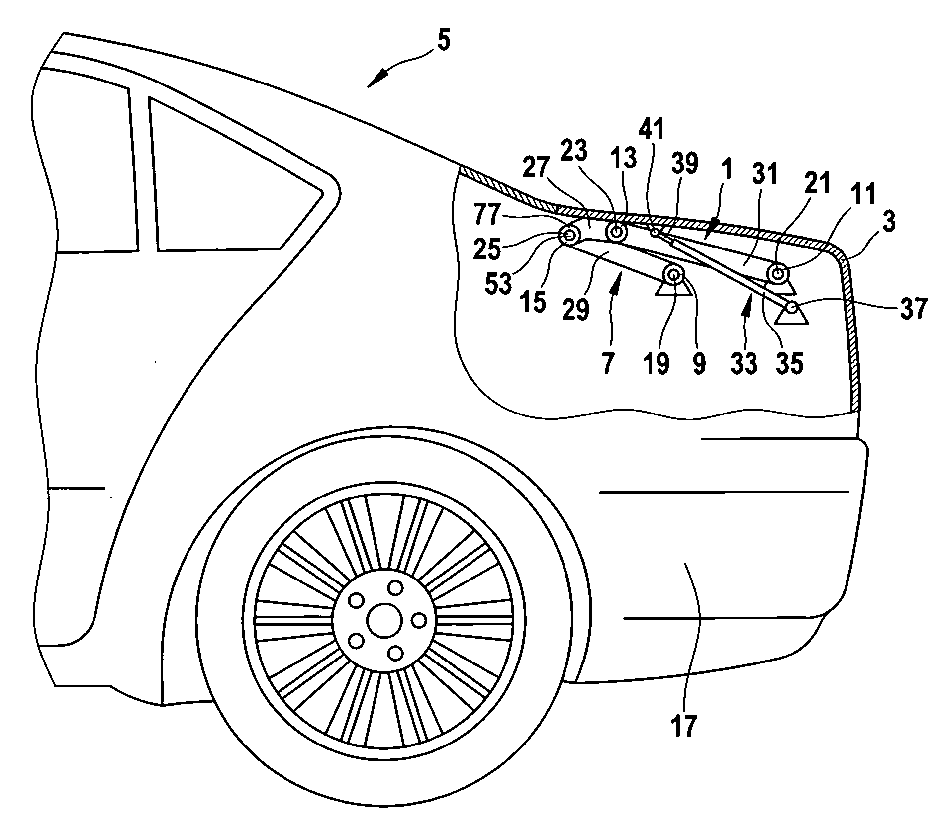
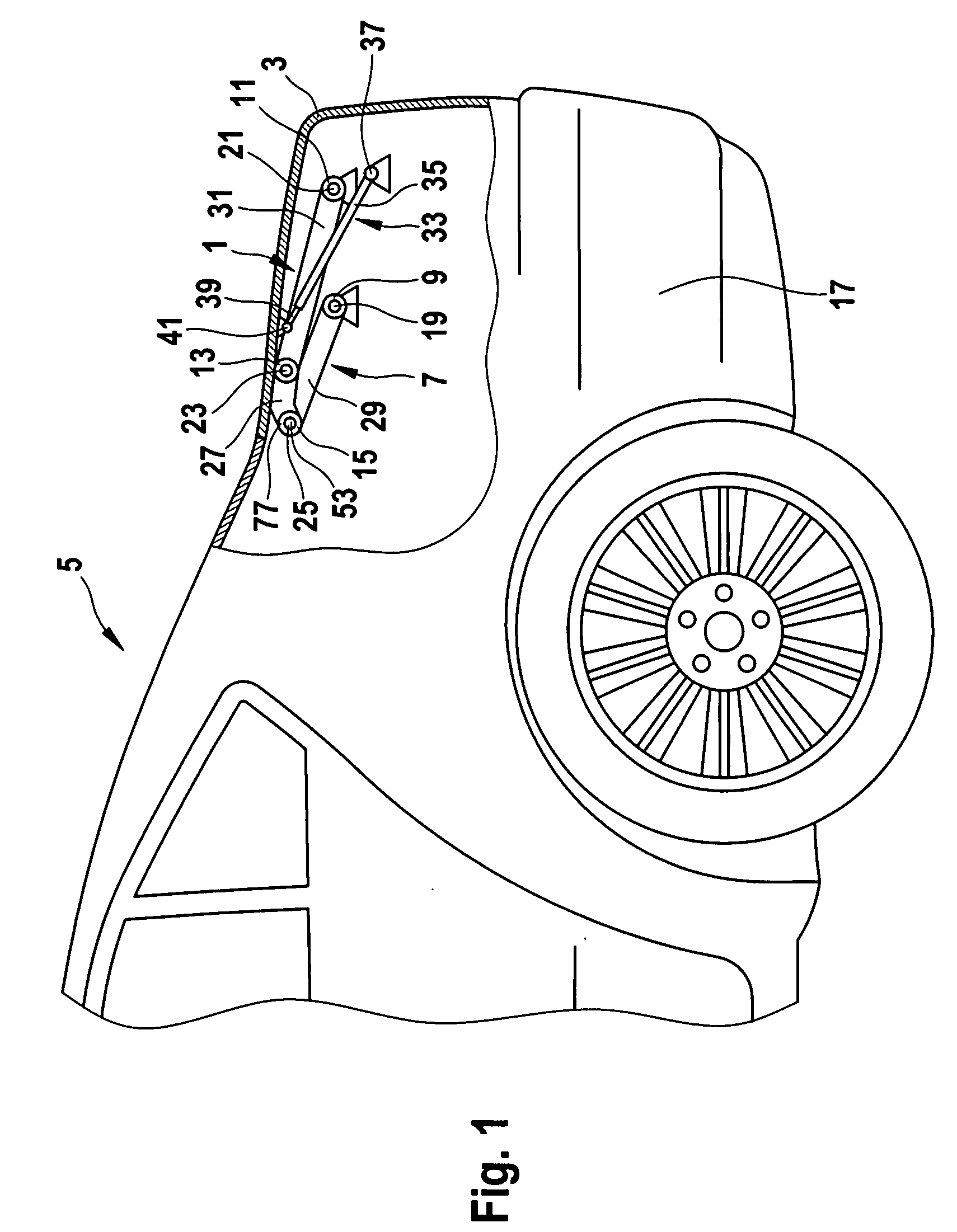
[0025]FIG. 1 shows a joint arrangement, especially a multi-joint hinge 1, for a panel 3 of a vehicle 5. The panel 3 here is the trunk lid of a passenger car. The joint arrangement 1 is designed to allow the panel 3 of the vehicle 5 to be moved between a closed position and an open position. FIG. 1 shows the panel 3 in its closed position. The joint arrangement 1 of the vehicle 5 has a four-bar joint 7 with a first joint 9, a second joint 11, a third joint 13, and a fourth joint 15. The first and the second joints 9, 11 are permanently fastened to the body 17 of the vehicle 5. For this mounting, the first joint 9 has a first roller bearing 19, and the second joint 11 has a second roller bearing 21. The third joint 13 and the fourth joint 15 are permanently fastened to the panel 3 of the vehicle 5 and have for this purpose a third roller bearing 23 and a fourth roller bearing 25. The mounting of the third roller bearing 23 and of the fourth roller bearing 25 to the panel 3 is accompli...


PUM


Abstract

A multi-joint hinge for a motor vehicle having a body and a panel, the hinge allowing the panel to be moved between an open position and a closed position relative to the vehicle body. The hinge includes at joint having at least one roller bearing, and is preferably a four bar joint having two bearings mounted on the body and two bearings mounted on the panel.

Description

BACKGROUND OF THE INVENTION [0001] 1. Field of the Invention [0002] The invention pertains to a joint arrangement, especially a multi-joint hinge, designed to allow a panel of a vehicle to be moved between a closed position and an open position. Joint arrangements are used in particular for the opening and closing of panels of vehicles such as hoods, doors, rear hatches, and / or trunk lids. Such joint arrangements can have at least one rotary joint, which is assigned to the vehicle and to the corresponding panel to be moved, where the panel is supported with freedom to pivot with respect to the vehicle. [0003] 2. Description of the Related Art [0004] U.S. Pat. No. 6,669,370, for example, describes a plain bearing with a hinge housing part and a bearing pin, which is inserted into a pressed-in flange bearing bush. SUMMARY OF THE INVENTION [0005] An object of the invention is to provide an improved joint arrangement designed to allow a panel of a vehicle to be moved. [0006] In correspo...

Claims


Application Information

Patent Timeline
Patent Type & Authority Applications(United States)
IPC IPC(8): E05D11/10
CPCE05D3/145E05F1/1091Y10T16/54028E05Y2900/548E05Y2201/628
Inventor DARSCHEID, KARL-HEINZMINTGEN, ROLFKAISER, ALEXANDRARICKENBERG, TORSTEN
Owner STABILUS
Why Eureka
Try Eureka