Method, Tool and Apparatus for Producing Lamination Packs, and Lamination Pack

a technology of lamination packs and tools, applied in the manufacture/assembly of piezoelectric/electrostrictive devices, dynamo-electric machines, cores/yokes, etc., can solve the problems of increasing the cost and risk associated with methods, reducing the usefulness of methods, and increasing the number of pack types , to achieve the effect of facilitating the start, avoiding the cost of building a new tool

Active Publication Date: 2007-09-13
KIENLE & SPIESS STANZ UND DRUCKGIESSWERK
View PDF6 Cites 18 Cited by
  • Summary
  • Abstract
  • Description
  • Claims
  • Application Information

AI Technical Summary

Benefits of technology

[0026] One option is to control dispensing of the glue such that dispensing is interrupted when a new pack is to be started. This control can be linked to the press control, for example, in that dispensing of glue dots is prevented after a preset number of punches has been performed. This would result in laminations being produced without glue and thus would facilitate the start of a new pack in the restrictor.
[0027] A clear advantage of the inventive technique is that it does not rely on a physical connection for joining the parts. Therefore, the rotation of subsequent laminations can be realized at any angle required by the product.
[0028] It is possible to use the gluing technique to apply dots of glue to areas of the strip that will not appear on the finished lamination. This process could be used for part shapes that, when punched, create scrap parts that could exit the die and return into the tool thus creating potentially long-term breakdowns. Although the glue is not fully cured during the earlier stages of punching, the bonding action between the individual scrap parts is sufficient to prevent the scrap parts from returning into the tool. This problem relates both to certain materials and also certain shapes. Therefore, the present invention greatly increases the number of pack types that can be assembled within a tool.
[0029] One variant of this

Problems solved by technology

This so-called interlocking process has several disadvantages: (a) The interlocking technique requires manufacture of very complex tools whose parts are very sensitive with regard to material quality and are less robust than tools not to be used for interlocking laminations.
This increases the costs as well as the risks associated with the method; this may diminish its usefulness.
(b) Very thin sheet steel, for example, less than 0.35 mm thick, is difficult to interlock and this leads to low efficiency methods.
(d) A further disadvantage of the present interlocking technique resides in that materials of different thickness or properties (often characterized by different quality specifications) cannot be joined.
Various problems are associated with the various existing techniques for applying an adhesive onto the strip surface when used as an integral part of the core manufacture.
(a) The possible p

Method used


Image

  • Method, Tool and Apparatus for Producing Lamination Packs, and Lamination Pack
  • Method, Tool and Apparatus for Producing Lamination Packs, and Lamination Pack
  • Method, Tool and Apparatus for Producing Lamination Packs, and Lamination Pack

Examples


Embodiment Construction

[0039] In the following, a detailed description of how this technology could be implemented is provided. The drawings to which reference is being had are the above mentioned FIGS. 1 to 6. All reference numerals are shown in the drawings.

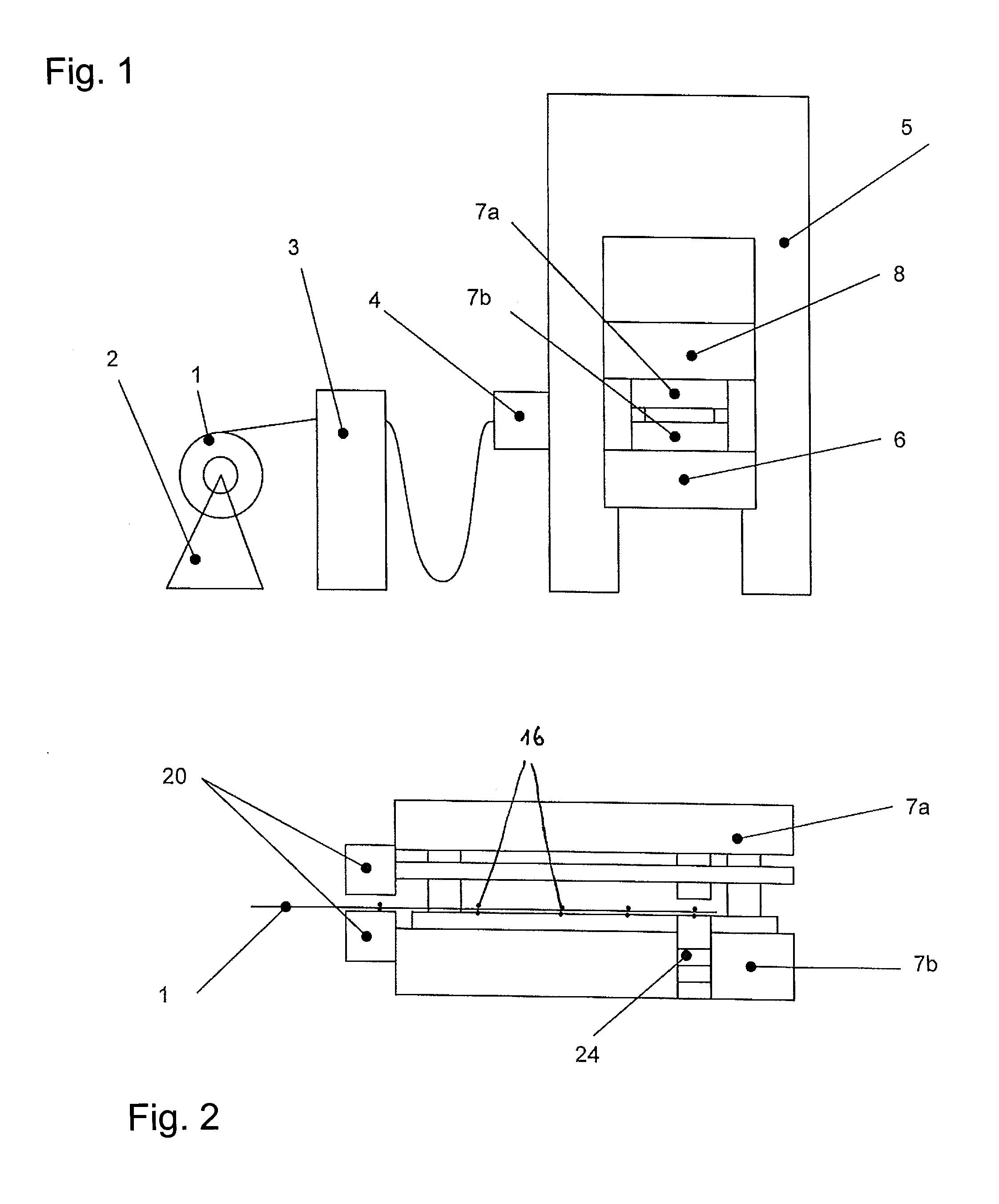
[0040]FIG. 1 shows a schematic diagram of a punching press. The coil of raw material 1 is arranged on the uncoiler 2. It is shown how the strip material is guided through a roller leveler 3 and then into the feeder 4 and into the press housing 5. The tool sits on the press table 6 and is comprised of two parts, the upper part 7a and the lower part 7b. The upper arm of the press 8 moves up and down to effect punching of the strip into laminations.

[0041] Some more details of the arrangement of the key elements inside the press housing are indicated schematically in FIG. 2. In this embodiment, the application unit is located at the front of the tool and can be attached either to the upper 7a or lower 7b part of the tool. The applicator valve operates ...


PUM

PropertyMeasurementUnit
Thicknessaaaaaaaaaa
Angleaaaaaaaaaa
Heightaaaaaaaaaa

Abstract

Lamination packs of a controlled height are produced in that laminations are punched with a tool and glue is applied partially onto at least one of an upper surface and a lower surface of each of the laminations without the application device that applies the glue contacting the laminations. Several of the laminations are then assembled to a lamination pack. Height of the lamination packs is controlled by interrupting the application of glue for certain laminations so that between some of the laminations that are stacked for assembling a lamination pack there is no glue.

Description

BACKGROUND OF THE INVENTION [0001] The invention concerns a method for manufacturing lamination packs in a tool for punching laminations onto which laminations glue is applied and which laminations are assembled to a lamination pack. The invention also concerns a tool for producing lamination packs according to said method and an apparatus for producing lamination packs according to said method. [0002] Electrical machines often use cores of stacked laminations that are manufactured from cut electrical sheets. Typically, a punching press is used in order to cut the individual laminations. The manufacture of the core or of the pack can be done in several ways, including mechanical joining of the parts in the press for forming the cores, welding, gluing, or mechanical joining of the laminations into packs outside of the press. [0003] Examples of prior patents in the field of manufacturing packs outside of tool and press are disclosed in GB 1 501 676. This reference discloses how packs ...

Claims


Application Information

Patent Timeline
IPC IPC(8): H02K15/00H04R17/00B23P19/00
CPCB21D28/22H02K15/02Y10T29/5317Y10T29/42Y10T29/49075Y10T29/49078
Inventor BLOCHER, DANIELBAUER, STEFFEN
Owner KIENLE & SPIESS STANZ UND DRUCKGIESSWERK
Why Eureka
Try Eureka