Blender

a blender and dreg technology, applied in the field of blenders, can solve the problems of oxidizing important nutrients more quickly, reducing the efficiency of blending, and defeating the purpose of pulverizing or juicing, so as to reduce the volume of the blender and reduce the cost of material production. , the effect of reducing the cost of material cost in manufacturing

Inactive Publication Date: 2007-09-13
CHANG MING SHIH
View PDF9 Cites 68 Cited by
  • Summary
  • Abstract
  • Description
  • Claims
  • Application Information

AI Technical Summary

Benefits of technology

[0018] After the blade disk cover added below the feed chute of the upper housing, shredded fruits can be macerated between the blade disk cover and the blade disk, because first, second gaps kept between them, the shredded fruits can be macerated to form pulp contained juice.
[0019] The sieve is mainly constructed by a base impervious to water and a frame may be adorned with grids or meshes as a wall to surround the base. Though getting pulp contained juice is first flowing to the sieve, most of pulps still can be led into the container through the sieve to preserve nutrients without introducing air, further, the pulp remained within the sieve may not be oxidized to destroy nutrients in vegetable or fruit.
[0020] Further, a dreg outflow hole 25 formed through an inner circle 21 of the blade disk 2, each crescent shaped dreg outflow hole 25 formed in front of each leading edge of a cambered blade 23 respectively. The dreg outflow hole 25 is preferrable a little larger than the blade 23, before grinding a fruit or vegetable through the blades 23, slumps of a fruit or vegetable may be divided by the leading edges. After that, most of the sliced fruit or vegetable can be thrown out to the outer circle for a further grinding job, however, morsels or dregs of shredded vegetable or fruit may be built up and clogged with the inner circle, those morsels or dregs can be expelled out downwardly from the holes 25. Thereby, pulps contained juice may be produced throughout the inner and outer circles more efficiently; a sufficient supply of pulps contained juice can be proficiently gotten from such a dreg outflow disk.
[0021] After combination of the disk 2 and a base 3, an outflow space A kept between them is sufficient for expelling the dregs from the hole 25 normally.
[0022] Even an area of the disk 2 is reduced, further, the volume of the blender can be reduced, as a result, the blender is not designed as an enormous space-occupied apparatus, in use, it can be brought in person at one's convenience. Even the material cost in manufacturing can be cost down, and space-economy is fulfilled. Further, an aperture of the feed chute can be formed circular in shape; a fruit or vegetable for getting a pulp may pass through the feed chute promptly and easily.

Problems solved by technology

However, faster moving parts introduce more air into the pulp and juice, and therefore oxidize important nutrients more quickly.
It has also been said that the heat generated from the machine and the friction of centrifugal juicers destroy enzymes found only in raw vegetables and fruits (because of the damage done during the cooking or heating process), thereby defeating the purpose of pulverizing or juicing.
Those blades and teeth arrayed to form inner and outer circles are not suitable for reducing pulps or dregs occasionally built up therein, even the pulp contained juice or dregs are not pulverized as desired.
However, the disk of TW493417 is mainly divided into an inner and an outer circles, what is chopped through the inner circle must be implemented by a centrifugal force to dispel to the outer circle; and the plunger of U.S. application Ser. No. 10 / 972,469 inserted into a feed chute in any orientation by similar magnets installed thereto, whose magnetic field only attracted by steel or the like, it could be interfered with edible vegetable grease or others build up and being clogged with the plunger or the channel continual disregard magnetism or the like up for safety mechanism.

Method used


Image

  • Blender
  • Blender
  • Blender

Examples


first embodiment

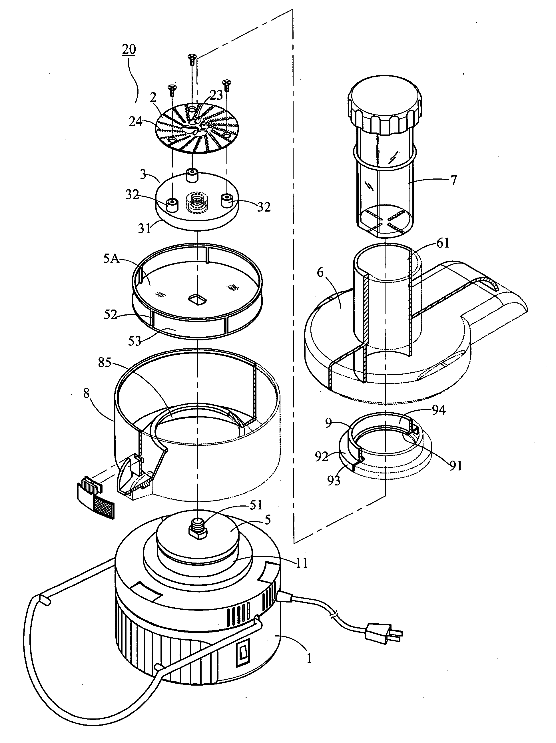
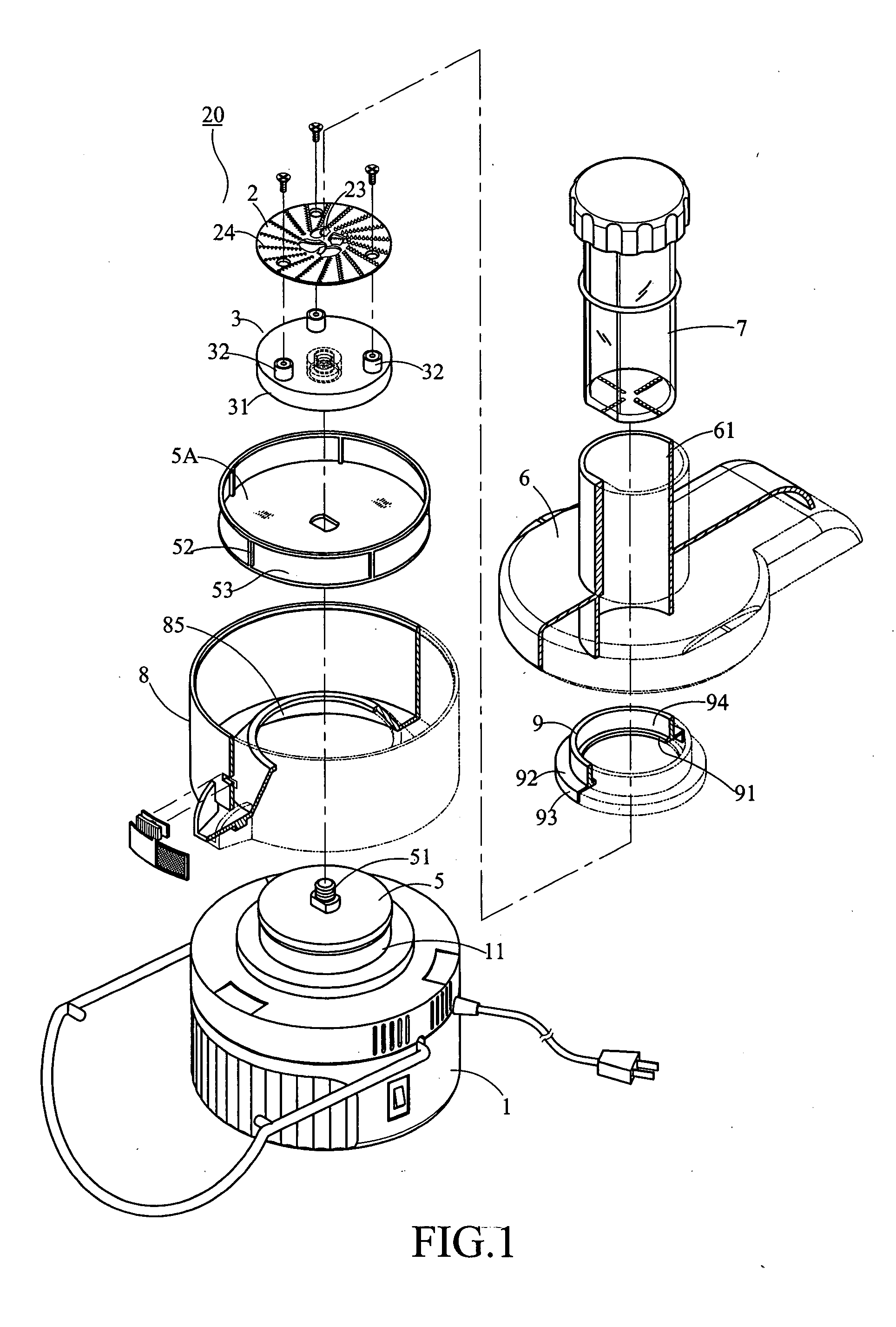
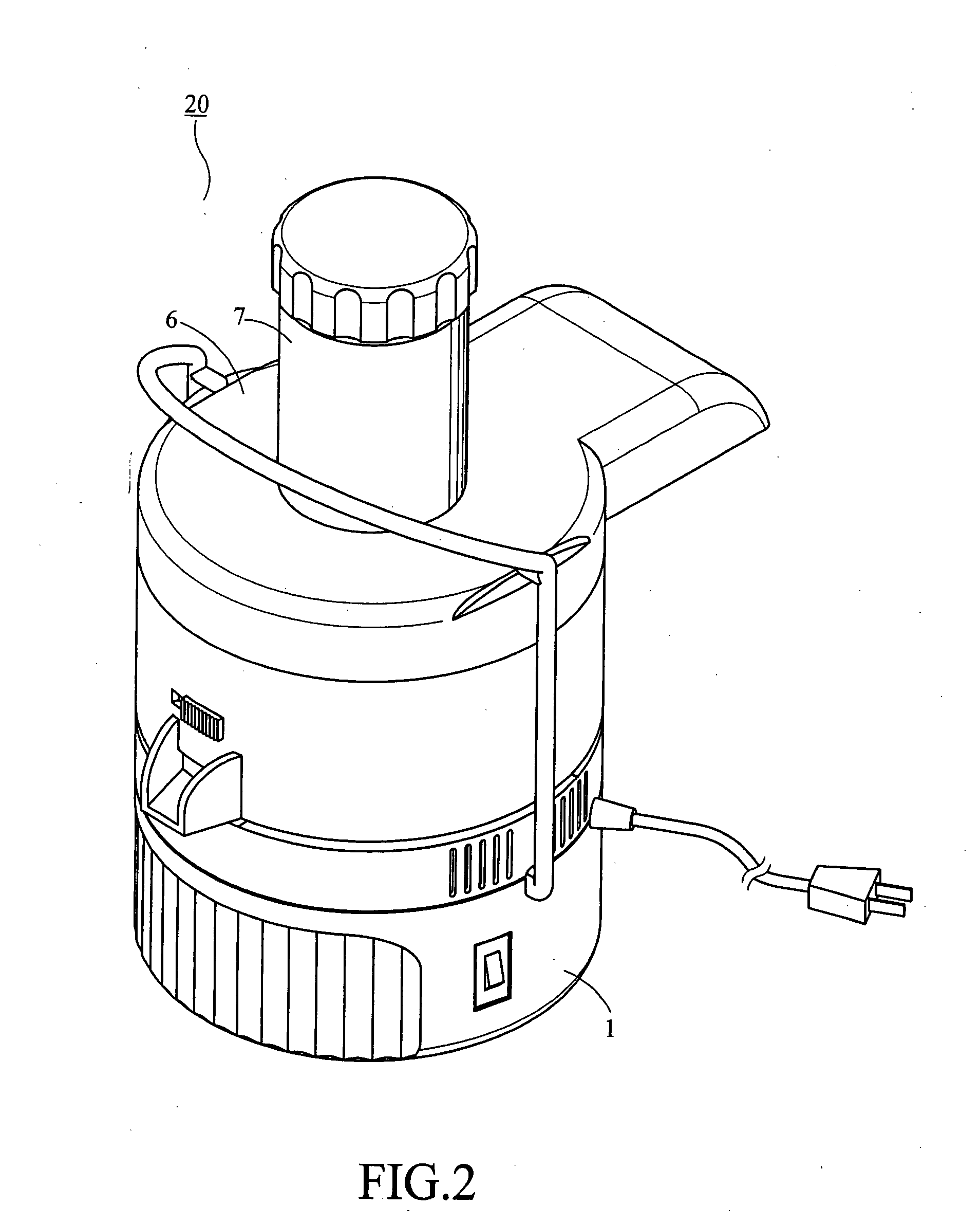
[0035] As shown in FIG. 1, a first embodiment of the present invention is illustrated. In that, a blender 20 includes a lower housing 1 having a motor 11 with a shaft 51 mounted inside thereof, a base 3 assembled to the shaft 51 of the motor 11 as a whole, a ring type container 8, a blade disk 2, a sieve 5A with a frame 52 and a base 53, an upper housing 6 with a feed chute 61 having an aperture circular in shape centrally formed therethorugh, and a plunger 7. Further a ring type blade disk cover 9 is added below the feed chute 61 further being extended above the blade disk 2. After assemblage, the assembled blender is illustrated as shown in FIG. 2.

[0036] Once the ring type blade disk cover 9 assembled to the feed chute 61, the sieve 5A with the frame 52 for temporarily storing dregs or pulps, the frame may be adorned with meshes or grids, further can be shaped as a wall 52 instead of the frame surrounds the base 53 (illustrated as in FIG. 1) to collect fresh and pulverized foodst...

second embodiment

[0040] As shown in FIGS. 4 and 5, a ring type blade disk cover 9 is assembled to the feed chute 61 different from the first embodiment. Two plastic buttons 95 projected inwardly from a central bore 94 of the ring type blade disk cover 9 can be embedded into two corresponding troughs 64 formed along an outer wall of the feed chute 61. A vertical tenon 96 projected inwardly from the central bore of the ring type blade disk cover 9 can be glided along a vertical trough 65 formed along an outer wall of the feed chute 61, the tenon 96 can be led into the trough 65 to eliminate rotated movements between the ring type blade disk cover and the feed chute.

third embodiment

[0041] As shown in FIGS. 7 and 8, a disk assembly 1 comprises a blade disk 2 made of stainless steel and a base 3 made of plastic steel, the disk and the base are secured to each other by screws 4 coupled to props 32 inside the base 3, the base 3 also has a central nut, thereby, the base can be assembled to a shaft 51 of a motor 11.

[0042] As shown in FIGS. 9 and 10, the blade disk 2 is circular in shape, an inner circle 21 and an outer circle 22 to a rim of the blade disk 2 (please see FIG. 10) are configured on an upper surface of the blade disk 2, the inner circle 21 having cambered blades 23 arranged as an intermittent loop or approximately shaped as a cross at a central smaller area of the blade disk 2, the outer circle 22 surrounds the inner circle to a rim of the blade disk 2 is occupied a larger area, a number of teeth 24 are radiated from the inner circle to the rim of the blade disk 2.

[0043] The blade disk 2 is punched to form a number of blades and teeth protruded out fr...


PUM


Abstract

The present invention is related to a blender, particularly to a blender having a blade disk formed with dreg-expel holes in front of leading edges of blades of inner circle, and a ring-typed cover added below a feed chute as well as being hung over the blade disk to keep gaps in between, thereby it can get pulp contained with juice; which introduces less air thereinto, further enzymes found in raw vegetables and fruits may not be destroyed.

Description

CROSS REFERENCE TO RELATED APPLICATION [0001] The present invention is a C-I-P application related to the application assigned Ser. No. 10 / 946,551 published on Mar. 23, 2006, Ser. No. 11 / 410,907 published on Aug. 31, 2006, Ser. No. 11 / 341,424 filed on Jan. 30, 2006 now is abandoned. FIELD OF THE INVENTION [0002] The present invention is related to a blender, particularly to a blender having a blade disk formed with dreg-expel holes in front of leading edges of blades of inner circle, and a ring-typed cover added below a feed chute as well as being hung over the blade disk to keep gaps in between, thereby it can get pulp contained with juice; which introduces less air thereinto, further enzymes found in raw vegetables and fruits may not be destroyed. GROUND OF THE INVENTION [0003] To squeeze fruit or vegetable, for a pulp contained juice is popular to serve as healthy foodstuff and fresh ingredients added to fruit pies, cake decorations, or appetizers, even being processed as nutriti...

Claims


Application Information

Patent Timeline
Patent Type & Authority Applications(United States)
IPC IPC(8): A23N1/00
CPCA47J19/027A47J43/0722
Inventor CHANG, MING-SHIH
Owner CHANG MING SHIH
Why Eureka
Try Eureka