Flying wing rotation mechanism of micro air vehicle

a micro-air vehicle and wing rotation technology, applied in the field of micro-air vehicles, can solve the problems of difficult to precisely describe the airflow activity in 3d space, difficult for people to fully realize, and complex, etc., and achieve the effect of simple structure and easy miniaturization

Inactive Publication Date: 2007-09-13
LIAO WEI HSIANG
View PDF22 Cites 43 Cited by
  • Summary
  • Abstract
  • Description
  • Claims
  • Application Information

AI Technical Summary

Benefits of technology

[0013] Accordingly, the present invention discloses a flying wing rotation mechanism of a

Problems solved by technology

However, they have not yet been completely and fully realized.
The difficulties lie in that it is difficult for people to precisely describe airflow activities in 3D space, especially the airflow phenomena around the wings of the insects.
The wings of the insects are very small, flutter rapidly, and are very complicated.
However, the above two approaches cannot explain the motion that an insect takes off or hangs in the air, and cannot depict the flying of the i

Method used


Image

  • Flying wing rotation mechanism of micro air vehicle
  • Flying wing rotation mechanism of micro air vehicle
  • Flying wing rotation mechanism of micro air vehicle

Examples


Embodiment Construction

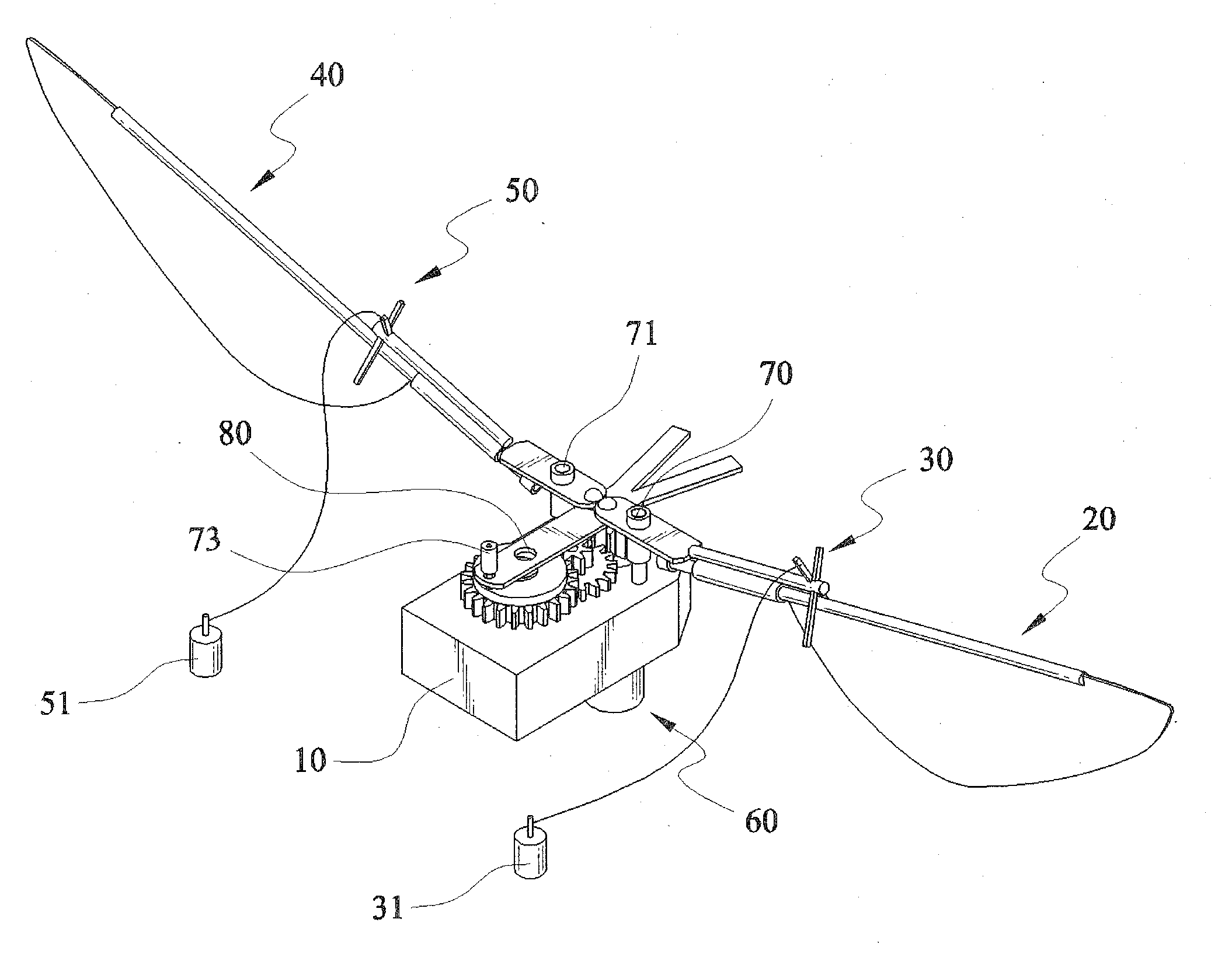
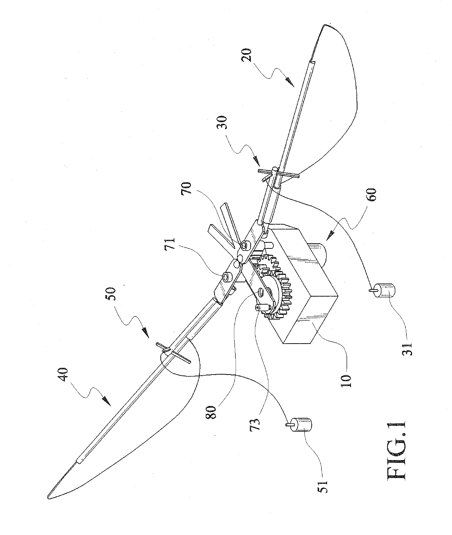
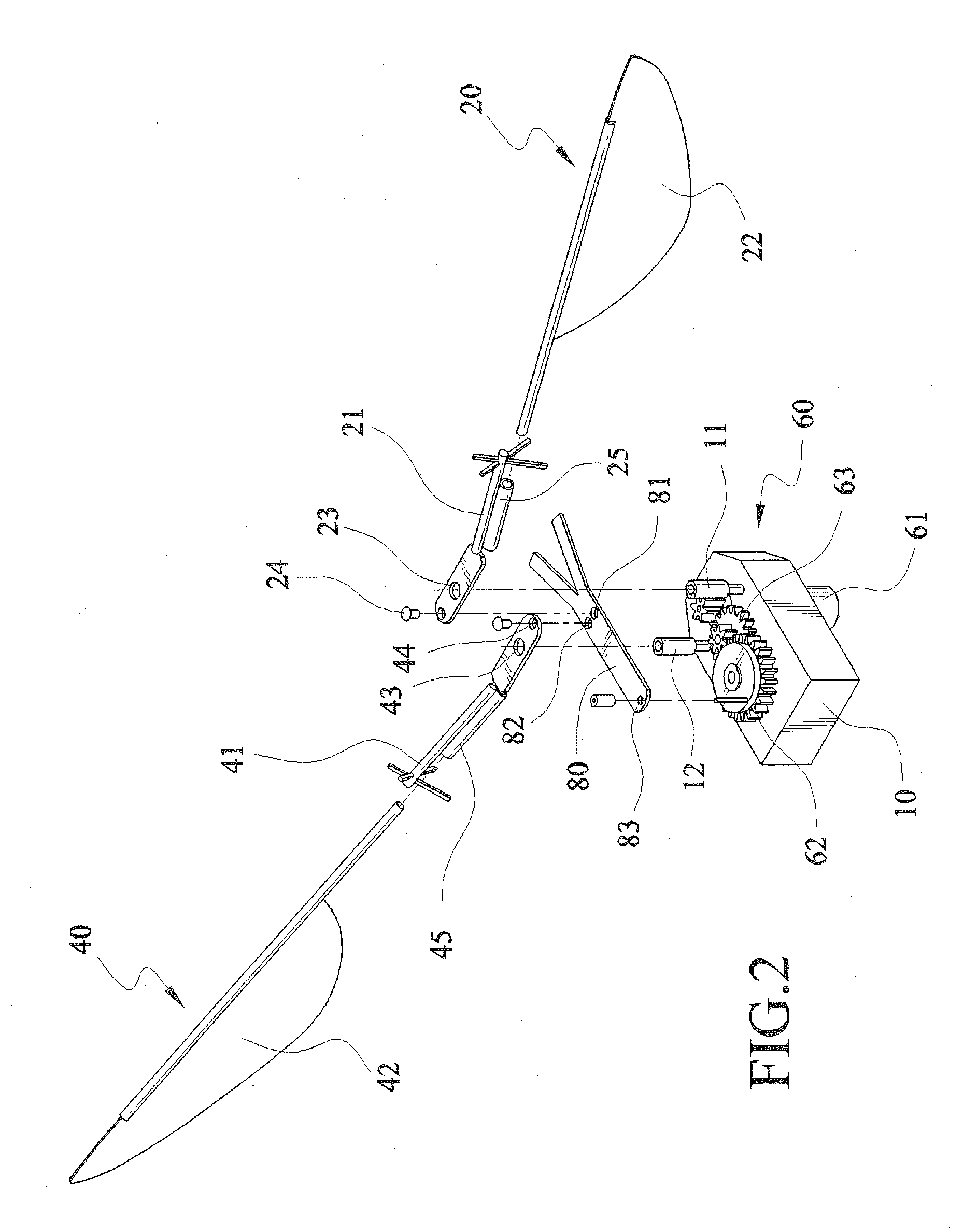
[0033] Referring to FIGS. 1-5, main components, structural features, and actuation modes of the micro air vehicle are illustrated before describing the flying wing rotation mechanism of a micro air vehicle according to the disclosure of the present invention.

[0034] The micro air vehicle of the preferred embodiment of the present invention mainly includes a body 10, a first flying wing set 20, a first angle controller 30, a second wing set 40, a second angle controller 50, a detent member 80, and a power module 60. A right shaft 11 and a left shaft 12 are arranged on the body 11. The first flying wing set 20 is disposed on the right of the body 10, and mainly includes a first flapping arm 21 and a first flying wing 22. A first through hole 23 and a first locking hole 24 are opened in an end of the first flapping arm 21. The bottom of the first flapping arm 21 extends to form a long cylinder 25. The first flying wing 22 is pivoted to the first flapping arm 21 through the long cylinde...


PUM


Abstract

A flying wing rotation mechanism of a micro air vehicle is driven under a control of a power module and a detent member. The flying wing rotation mechanism of a micro air vehicle includes a flapping arm and a flying wing. The flapping arm is connected to the detent member, and swings as the power module drives the detent member. An end of the flying wing is pivoted to the flapping arm. When the flapping arm swings, the flying wing swings with the flapping arm in sync. When swing direction of the flapping arm changes, the flying wing rotates relative to an axial direction of the flapping arm.

Description

CROSS-REFERENCE TO RELATED APPLICATIONS [0001] This application is a continuation-in-part patent application of U.S. application Ser. No. 11 / 367,377 filed on Mar. 6, 2006, the entire contents of which are hereby incorporated by reference for which priority is claimed under 35 U.S.C. § 120.BACKGROUND OF THE INVENTION [0002] 1. Field of Invention [0003] The present invention relates to a micro air vehicle, and more particularly to a flying wing rotation mechanism of a micro air vehicle. [0004] 2. Related Art [0005] Flying motions of insects imply profound knowledge. [0006] Taking common drosophila as an example, the flying motions of the drosophila include rapid taking off, circling, diving, and sharp turning etc. These excellent flying skills enable the drosophila to attack and get food easily, and to escape from people at the same time. [0007] How can the drosophila do this? The thin wings of insects are distinctively different from big wings of birds. Experts in zoology, aviation, ...

Claims


Application Information

Patent Timeline
IPC IPC(8): B64C33/00
CPCB64C33/02B64C2201/025B64C39/028B64U10/40B64U50/19B64U10/80
Inventor LIAO, WEI-HSIANG
Owner LIAO WEI HSIANG
Why Eureka
Try Eureka