Finger tongs

Inactive Publication Date: 2007-09-13
FUSIONBRANDS
View PDF23 Cites 19 Cited by
  • Summary
  • Abstract
  • Description
  • Claims
  • Application Information

AI Technical Summary

Benefits of technology

[0033]Gripping bands for increasing the gripping ability for larger or slippery items, formed behind the gripping teeth elements
[0034]One aspect of the present invention is that it may be

Problems solved by technology

This type of mitt is not designed to easily slide under a chicken breast and flip it without splattering, creating a potential mess or grease fire hazard.
While these devices fulfill their respective, particular objectives and requirements

Method used


Image

  • Finger tongs
  • Finger tongs
  • Finger tongs

Examples


Embodiment Construction

[0054]The present invention will now be described in detail with reference to a few preferred embodiments thereof as illustrated in the accompanying drawings. In the following description, numerous specific details are set forth in order to provide a thorough understanding of the present invention. It will be apparent, however, to one skilled in the art, that the present invention may be practiced without some or all of these specific details. In other instances, well known operations have not been described in detail so not to unnecessarily obscure the present invention.

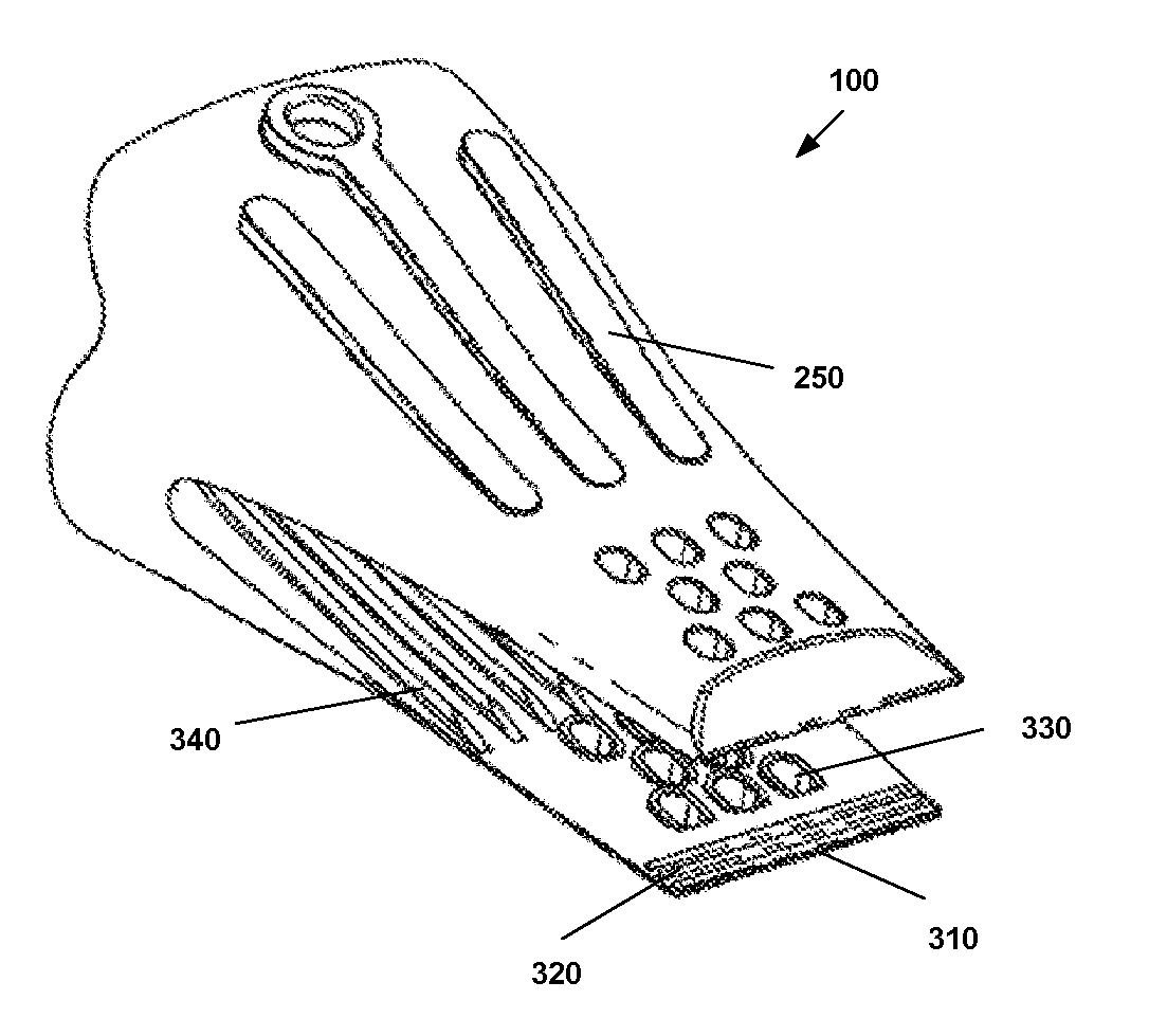
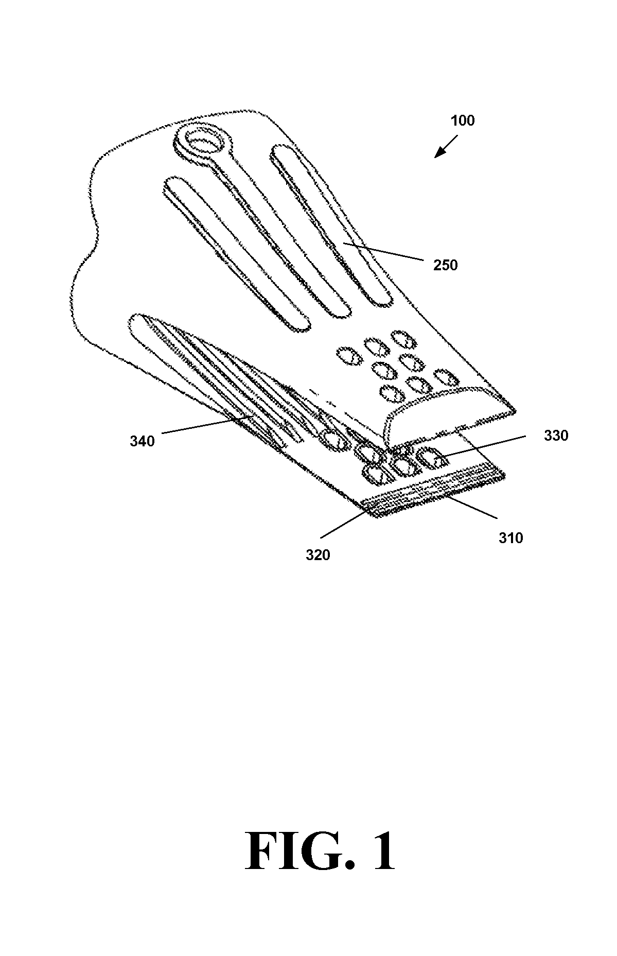
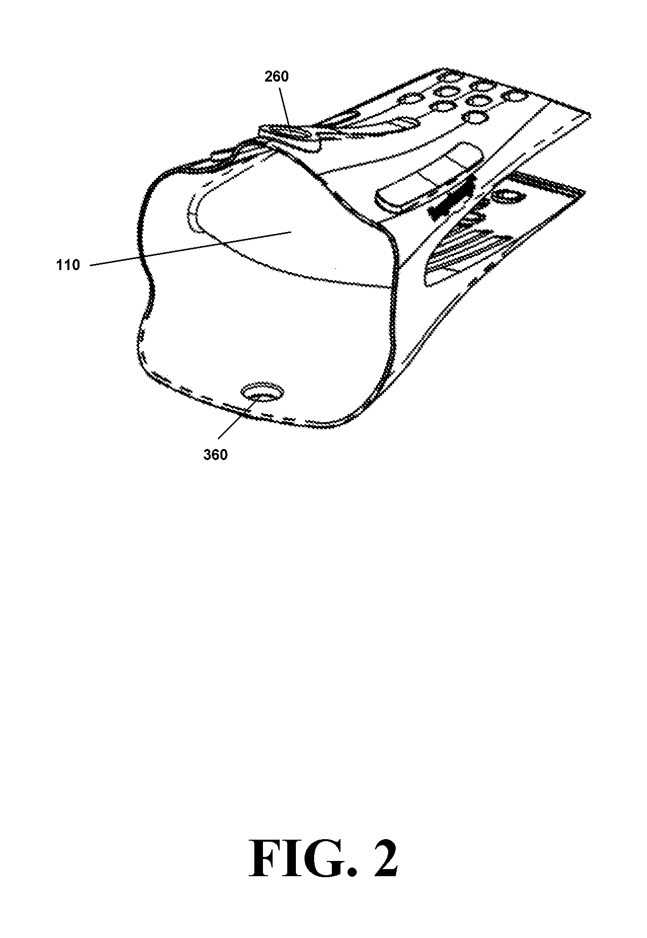
[0055]Referring now to FIG. 1 through FIG. 10 an embodiment of a finger tongs device 100 is comprised of a front tong element 200 flexibly hinged to a rear tong element 300 to form a seamless one piece structure, e.g., by a molding process having an internal cavity 110. In an exemplary embodiment the material of finger tongs device 100 is a flexible material that resists the high temperatures found in most cooking s...


PUM


Abstract

A kitchen accessory that combines features of tongs and a heat protective oven mitt is disclosed. The kitchen accessory consists of a front tong element flexibly hinged to a rear tong element to form a seamless one piece structure. Additional elements include scooping tips, different sized and shaped gripping and grasping elements, and heat shrink hand protectors. each other and connected to a hinge point surrounded by a hand protection area.

Description

[0001]This application claims the benefit of the filing date of and is a continuation-in-part of United States Design Patent Application having a title of FINGER TONGS, filed on Mar. 11, 2006 and assigned Ser. No. 29 / 255,624.FIELD OF THE INVENTION[0002]The present invention relates to the field of kitchen utensils, and more particularly to glove like devices for handling hot items.BACKGROUND OF THE INVENTION[0003]There are many kinds of food serving tongs and food handling gloves in present day use. Among the most familiar tongs is the simple sheet metal tongs composed of two identical opposing arms joined at one end by a pin and biased in the open position by a spring metal member inside the handles. Other well known tongs include the scissors type or those that are molded as one continuous piece of resilient plastic. Serving tongs such as these are often used at salad bars in restaurants and in serving other types of food in self-service food establishments, as well as for serving...

Claims


Application Information

Patent Timeline
IPC IPC(8): A47G21/10
CPCA41D13/081A47G21/10A47J45/10A47J43/283A47J36/04
Inventor STEWART, ANNA M.STEWART, STEPHEN KRAIGH
Owner FUSIONBRANDS
Why Eureka
Try Eureka