Battery, assembled battery unit, vehicle equipped with battery, and battery voltage adjusting method

a battery and battery technology, applied in the field of batteries, can solve the problems of reducing the life span limiting the performance of the overall bipolar battery, and reducing the performance of the battery as a whole, so as to improve the performance of the battery and improve the battery performan

Active Publication Date: 2007-09-13
NISSAN MOTOR CO LTD
View PDF4 Cites 22 Cited by
  • Summary
  • Abstract
  • Description
  • Claims
  • Application Information

AI Technical Summary

Benefits of technology

[0011]Accordingly, one object of the present invention is to provide a battery or an assembled battery including a plurality of batteries which can improve the performance of the battery as a whole by adjusting the voltage variation between the cells or the batteries. Moreover, another object of the present invention is to provide a

Problems solved by technology

If the voltages vary between the cells while the bipolar battery is in use, then the performance of the cell with the lowest voltage will limit the performance of the overall bipolar battery.
In addition, such variations in the cell performances will degrade the performance and reduce the life span of the battery as a whole.
Howeve

Method used


Image

  • Battery, assembled battery unit, vehicle equipped with battery, and battery voltage adjusting method
  • Battery, assembled battery unit, vehicle equipped with battery, and battery voltage adjusting method
  • Battery, assembled battery unit, vehicle equipped with battery, and battery voltage adjusting method

Examples


second embodiment

[0061]Referring now to FIGS. 5 to 9, a secondary battery 100A, an assembled battery module 250 (assembled battery unit), an assembled battery component 300 and an electric vehicle 400 in accordance with a second embodiment will now be explained. In view of the similarity between the first and second embodiments, the parts of the second embodiment that are identical to the parts of the first embodiment will be given the same reference numerals as the parts of the first embodiment. Moreover, the descriptions of the parts of the second embodiment that are identical to the parts of the first embodiment may be omitted for the sake of brevity.

[0062]In the second embodiment of the present invention, the assembled battery module 250 includes a plurality of the secondary batteries 100A (battery elements) connected in series. Moreover, the assembled battery module 250 has a plurality of resistors 350. These resistors 350 are configured and arranged to constantly discharge electricity from eac...

working example

[0088]A working example of the battery according to the present invention will now be explained. However, the present invention is not limited to this working example.

Formation of Electrodes

[0089]First, one surface of a stainless steel foil (SUS foil), which is the collector that has a thickness of 20 μm, was coated with the positive electrode slurry and then dried to form the positive electrode layer that had a film thickness of 15 μm. The positive electrode slurry was a mixture of LiMn2O4 (85% by mass) (positive electrode active material), acetylene black (5% by mass) (conducting assistant), PVDF (10% by mass) (binder), and NMP (slurry viscosity adjusting solvent).

[0090]Next, the opposite surface of the collector (SUS foil), which is the surface that is opposite the surface whereon the positive electrode layer was coated, was coated with the negative electrode slurry and then dried to form the negative electrode layer that had a film thickness of 15 μm. The negative electrode slur...


PUM


Abstract

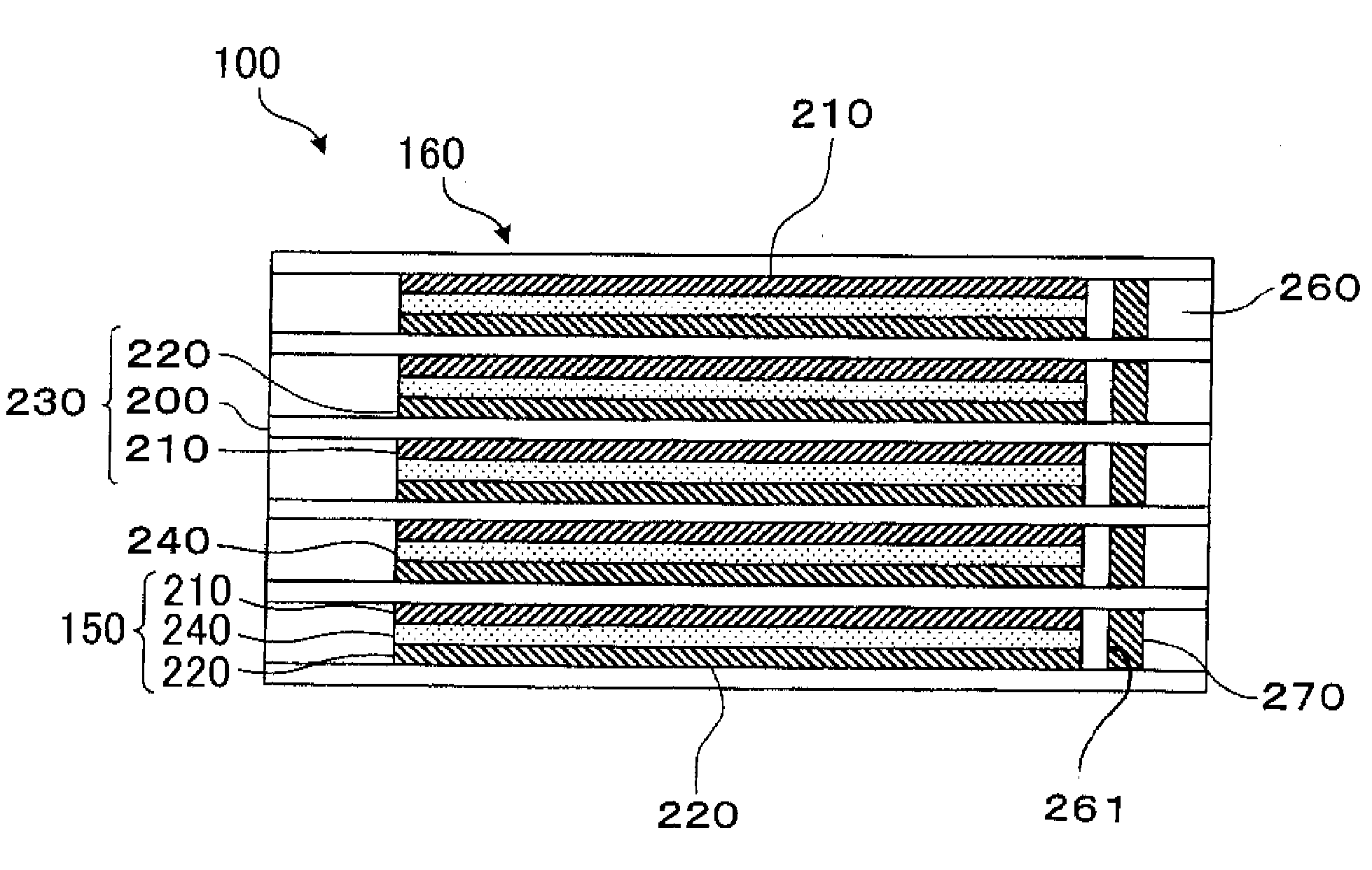
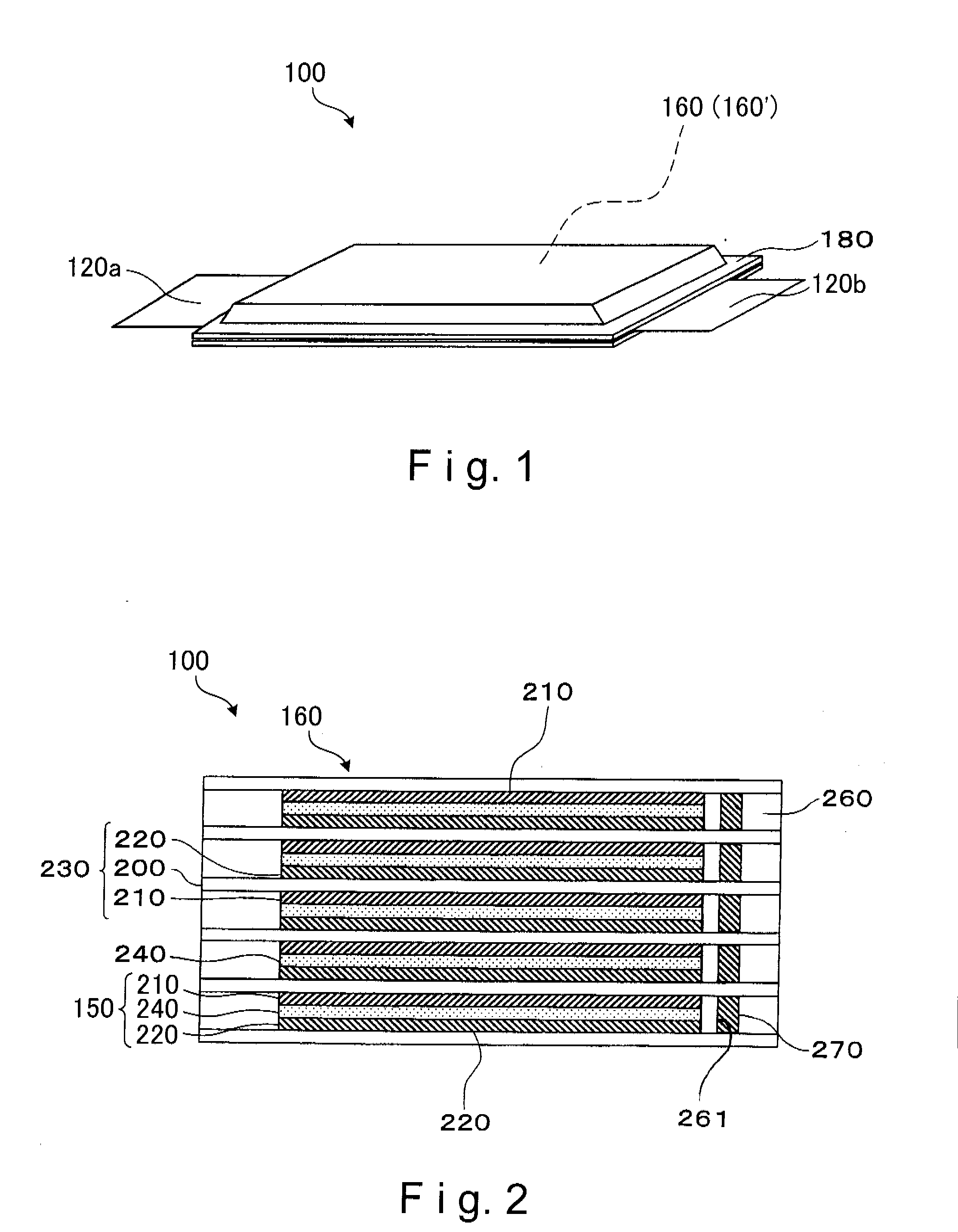
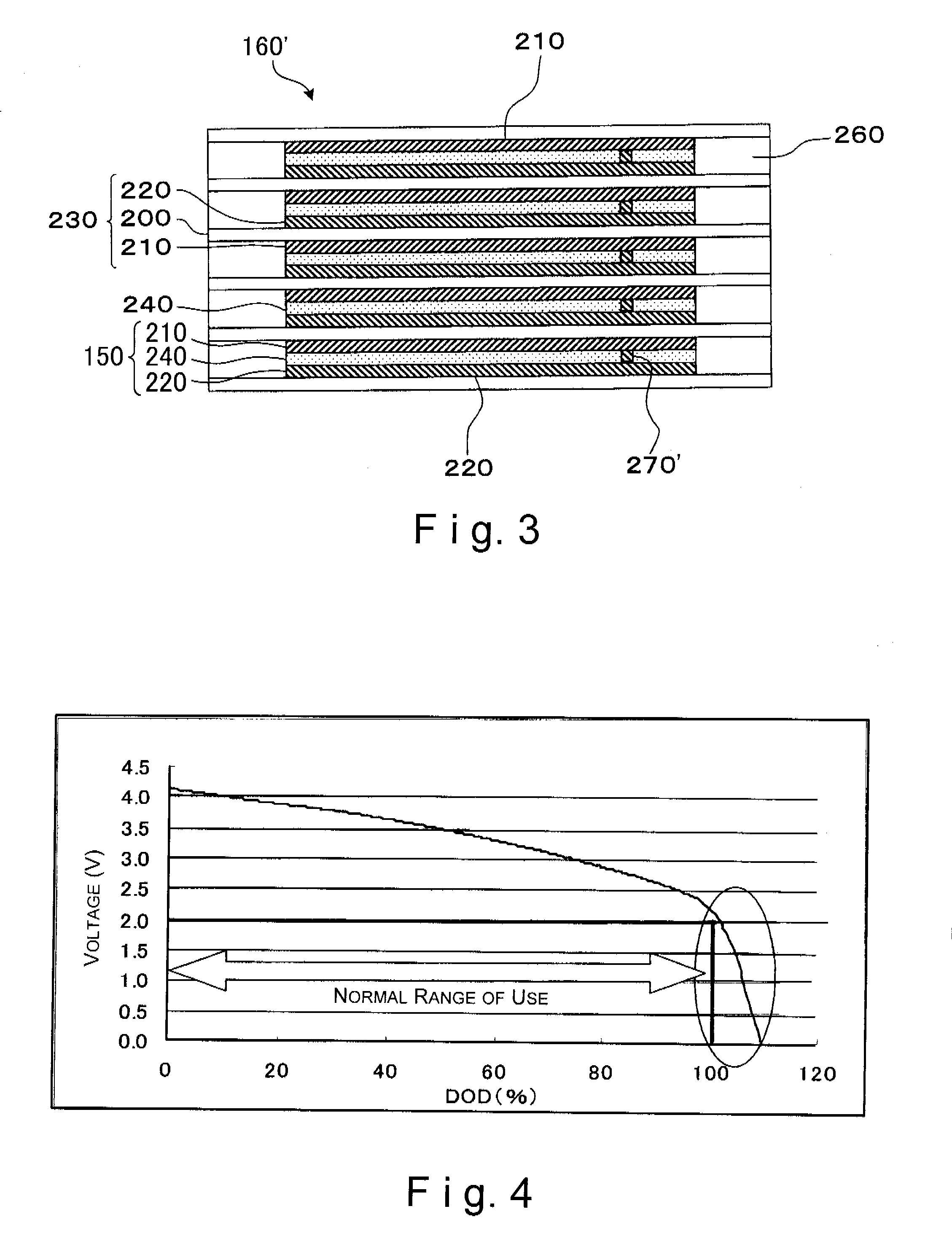
A battery is basically provided with an electricity generating element and a discharging section. The electricity generating element has a plurality of electric cells connected in series. The discharging section constantly discharges electricity from each of the electric cells at a prescribed discharge rate so that a voltage in each of the electric cells is lower than a voltage corresponding to a prescribed depth of discharge. The battery is especially useful in a power supply component of a vehicle.

Description

CROSS-REFERENCE TO RELATED APPLICATIONS[0001]This application claims priority to Japanese Patent Application No. 2006-064729, filed on Mar. 9, 2006 and Japanese Patent Application No. 2006-344894 filed on Dec. 21, 2006. The entire disclosures of Japanese Patent Application Nos. 2006-064729 and 2006-344894 are hereby incorporated herein by reference.BACKGROUND OF THE INVENTION[0002]1. Field of the Invention[0003]The present invention relates to a battery, an assembled battery, a vehicle equipped with a battery and a battery voltage adjusting method.[0004]2. Background Information[0005]A conventional vehicle battery is usually formed by connecting a plurality of secondary batteries in series. Recently, a bipolar battery has been used as the secondary battery installed in such a conventional vehicle battery.[0006]For example, Japanese Laid-Open Patent Application Publication No. 2000-195495 discloses a conventional bipolar battery that has a plurality of bipolar electrodes. Each of the...

Claims


Application Information

Patent Timeline
IPC IPC(8): H01M10/46H01M10/44H01M4/66H01M50/211H02J7/02
CPCH01M2/1077H01M10/0418H01M10/0525Y02T10/7011H01M10/425H01M10/441H01M10/4207H01M2220/20Y02E60/10Y02P70/50H01M50/211
Inventor SHIMAMURA, OASAMUHOSAKA, KENJIKINOSHITA, TAKUYAABE, TAKAAKIHORIE, HIDEAKI
Owner NISSAN MOTOR CO LTD
Why Eureka
Try Eureka