Channel form for a rotating pressure exchanger

Inactive Publication Date: 2007-09-13
KSB AG
View PDF9 Cites 13 Cited by
  • Summary
  • Abstract
  • Description
  • Claims
  • Application Information

AI Technical Summary

Benefits of technology

[0006] Another object of the invention is to provide a pressure exchanger in which reduced mixing losses occur during a pressure exchange.
[0009] In accordance with the invention, a flow guiding shape in the form of a channel contour that deflects the rotor channel flow is provided in the rotor channels, starting from or downstream from the openings. This flow guiding shape ensures impact-free oncoming flow to the rotor channels. As a result of this, flows with a uniform velocity distribution over a channel cross section are established in the rotor channels. Due to the uniform velocity distribution, development of flow components running across the channel flow in the channel cross section is prevented. Such flow components running transversely initiate development of eddies within a flowing column of liquid and running across the column, ultimately causing the mixing effect which occurs within the rotor channels. In systems, particularly desalination systems, in which production of a pure liquid is the goal, mixing is a deleterious aspect. The driving torque for the rotor is achieved by a direct transfer of momentum from the incoming flow and to a rotor end face through the impact-free flow deflection in the area of the channel openings. This is in complete contradiction with the approaches known in the past.
[0010] The risk of mixing in the rotor channels is further reduced if the shape provided in the inlet area of the rotor channels is constructed as a channel contour that makes the channel flow more uniformly. As a result, a velocity profile having an approximately homogeneous velocity field is established in 20-30% of the total length of a tube channel within a rotor channel downstream from the inlet area.
[0011] With the rotor channels, the inlet openings and / or the channel beginnings downstream from them have a shape that equalizes the flows in the rotor channels. This also yields a uniform velocity profile in the rotor channels, so that mixing of the two different pressure exchanging liquids in the rotor channels is minimized.
[0013] Such a design of the inlet of the rotor channels also includes the advantage that when there is a change in volume flow, the triangle diagram of the velocity at the inlet of the rotor channels undergoes an affine change, i.e., the circumferential component cu changes to the same extent as the oncoming flow velocity c of the liquid. Thus the driving torque acting on the rotor also increases, leading to an increase in the rotor rpm. With an increase in rotor rpm, the frictional moment acting on the rotor and having a retarding effect also increases. Due to the linear relationship between the driving torque MI which increases with an increase in the circumferential component cu and the frictional moment MR which increases in proportion to the rotational speed, the circumferential velocity of the rotor is always established so that the triangle diagrams of the velocity conditions which prevail at the rotor inlet are similar for all volume flows. There is thus a self-regulating effect which guarantees the condition of impact-free oncoming flow for each volume flow established. The rotational speed of the rotor is thus corrected based on the congruent velocity triangle diagrams and an impact-free oncoming flow of the rotor channels for volume flows of the main flows that are altered due to system conditions.

Problems solved by technology

This type of pressure exchanger is not equipped with an external drive.
To start operation, a complex method is required to cause such a pressure exchanger to start rotation of the rotor.
Disadvantages of this design include a restricted operating range and mixing of the two liquids, which are found alternately in the rotor channels during operation.
However, the disadvantages of this design include the arrangement, sealing and design of the ball, which acts as a separating element, and the respective seating.
In addition, a complex high-pressure seal is required as a shaft seal in the area of a shaft bushing for the external drive.

Method used


Image

  • Channel form for a rotating pressure exchanger
  • Channel form for a rotating pressure exchanger
  • Channel form for a rotating pressure exchanger

Examples


Embodiment Construction

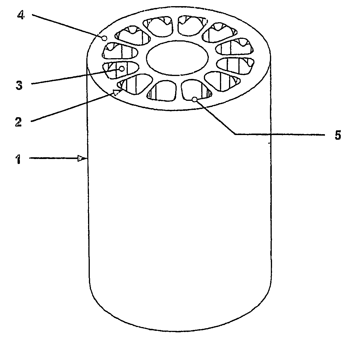
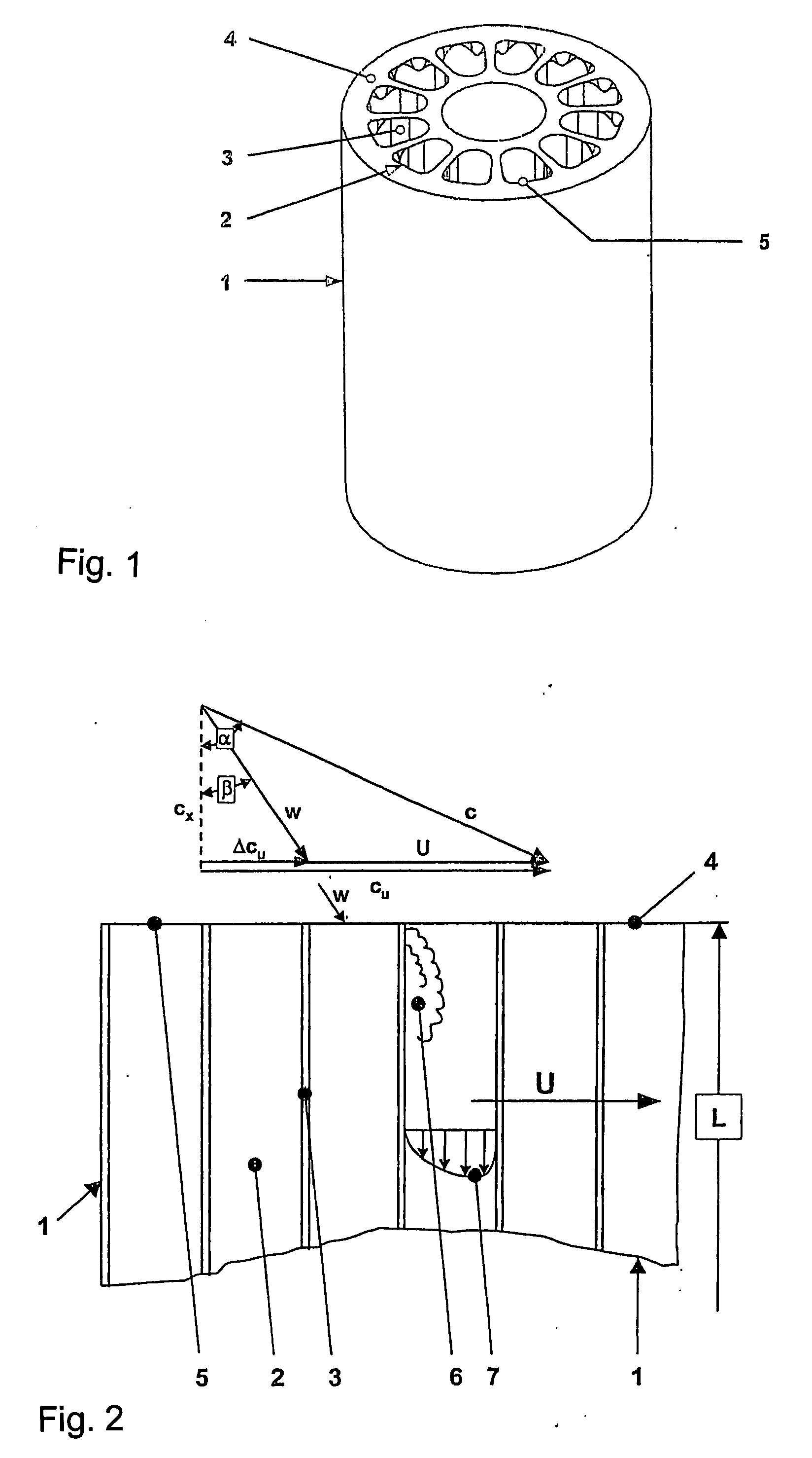
[0022]FIG. 1 shows a perspective view of a prior art cylindrical rotor 1 according to U.S. Pat. No. 6,540,487. Rotor channels 2 having a trapezoidal cross section are arranged so they are axially parallel to and concentric with the axis of rotation of the rotor 1, with wall surfaces 3 designed as webs running radially between the rotor channels 2 extending between the rotor channels 2. The openings 5 in the rotor channels 2 arranged on the end face 4 of the rotor 1 have additional rounded surfaces on their radially outer corners in the manner of inclined surfaces that widen diagonally outward, so that each opening is slightly enlarged. There is no diagram here of a housing surrounding the rotor or its connections for the lines, nor are the flow guiding transitions from the housing to the rotor shown here.

[0023]FIG. 2 shows the developed view of the rotor 1 of the prior art pressure exchanger illustrated in FIG. 1. Opposite the openings of the rotor 1 with its axially parallel rotor...


PUM


Abstract

A pressure exchanger for transferring pressure energy from a first liquid in a first liquid system to a second liquid in a second liquid system, having a housing with inlet and outlet connection openings for each liquid and a rotor (1) arranged in the housing for rotation about a longitudinal axis. A number of through rotor channels (2) are arranged around the rotor longitudinal axis with openings (4) on each axial end face of the rotor. The rotor channels (2) are arranged for connection through opposing flow openings formed in the housing to the connection openings of the housing such that during rotation of the rotor, high pressure liquid and low pressure liquid are alternately introduced into the respective systems. Liquid flowing to the rotor through the flow openings formed in the housing generates a circumferential force component (cu) in the relative rotating system of the rotor for driving the rotor, and starting at or following the openings (5) a flow guiding configuration (8) formed as a rotor channel flow diverting contour is arranged in the rotor channels (2).

Description

CROSS REFERENCE TO RELATED APPLICATIONS [0001] This application is a continuation of international patent application no. PCT / EP2005 / 007644, filed Jul. 14, 2005 designating the United States of America, and published in German on Feb. 16, 2006 as WO 2006 / 015681, the entire disclosure of which is incorporated herein by reference. Priority is claimed based on Federal Republic of Germany patent application no. DE 10 2004 038 439.8, filed Aug. 7, 2004.BACKGROUND OF THE INVENTION [0002] The present invention relates to a pressure exchanger for the transfer of pressure energy from a first liquid of a first liquid system to a second liquid of a second liquid system, comprising a housing with connector openings in the form of inlet and outlet openings for each liquid and a rotor arranged inside the housing to rotate about its longitudinal axis, said rotor having a plurality of continuous rotor channels with openings arranged around its longitudinal axis on each rotor end face, the rotor cha...

Claims


Application Information

Patent Timeline
IPC IPC(8): F04F11/00F04F99/00F04F13/00
CPCF04F13/00
Inventor BROSS, STEPHANKOCHANOWSKI, WOLFGANG
Owner KSB AG
Why Eureka
Try Eureka