Method for Producing a Polarizing Optical Element

a technology of polarizing optical elements and polarizing films, which is applied in the direction of coatings, coatings, applications, etc., can solve the problems of involuntarily, inability to reproduce, and involuntarily modify the color and polarizing effectiveness of the polarizing film, so as to achieve simple and inexpensive bonding

Active Publication Date: 2007-09-13
ESSILOR INT CIE GEN DOPTIQUE
View PDF1 Cites 14 Cited by
  • Summary
  • Abstract
  • Description
  • Claims
  • Application Information

AI Technical Summary

Benefits of technology

[0018] A second advantage of a method according to the invention lies in the fact that the multilayer structure may be produced on the temporary support in the form of a continuous film. A large quantity of the multilayer structure may thus be manufactured economically, by passing the temporary support through successive manufacturing sections. The structure, once separated from its support, may then be cut into segments that are individually applied to different optical elements. Alternatively, the structure may be applied in its entirety, at one time, to several different elements, then the elements may be subsequently separated from one another.
[0038] In addition, the possibility of depositing the PSA adhesive in the form of a thin layer with parallel faces, the thickness of which may be between 0.5 and 200 microns makes it possible, when the base optical element is an ophthalmic lens, not to impair its nominal power whatever the spatial region in question of the optical element. In this way, the bonding of the polarizing film is compatible with the precision that is necessary when the base optical element is a progressive ophthalmic lens.

Problems solved by technology

This limits the variety of polarizing film that can be used in this type of method.
In particular, its color and its polarizing effectiveness are modified involuntarily and in a not very reproducible manner.
Furthermore, it is difficult to prevent uncontrolled displacements of the polarizing film from occurring during the overmolding.
Finally, the overmolding method does not allow an optical element to be obtained that has an optimized reduced total thickness.
This is particularly irksome for high-refractive-index materials.

Method used


Image

  • Method for Producing a Polarizing Optical Element
  • Method for Producing a Polarizing Optical Element
  • Method for Producing a Polarizing Optical Element

Examples


Embodiment Construction

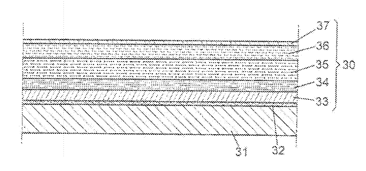
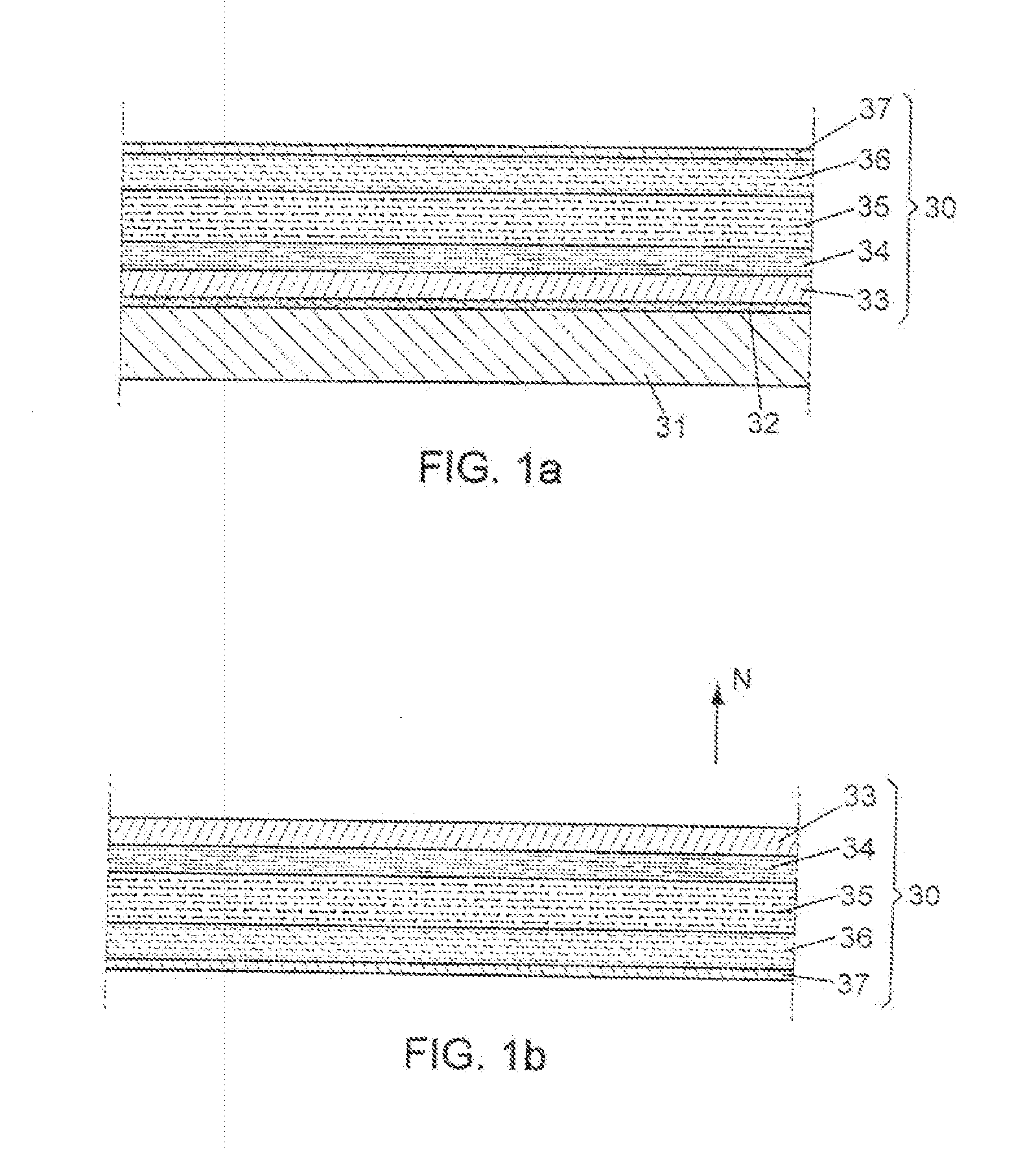
[0054] In accordance with FIG. 1a, a multilayer structure 30 is borne by a support 31. The support 31 is chosen from the materials having a surface energy that is between 25 mN / m (millinewtons per meter) and 40 mN / m. Among these materials, mention may be made by way of indication and nonlimitingly, of branched or linear polyethylenes, poly(ethylene-co-acrylic acid)s of which the percentage is mols of acrylic acid is less than or equal to 2, polyethylene-co-polypropylenes, poly(ethylene-co-vinyl acetate)s, polyisobutenes, polyisoprenes, poly(4-methyl-1-pentene)s, polypropylenes, poly(2-methylstyrene)s, polystyrenes, poly(styrene-co-acylonitrile)s, poly(styrene-co-2,2,3,3-tetrafluoropropyl methacrylate)s, polychlorotrifluoroethylenes, poly(chlorotrifluoroethylene-co-tetrafluoroethylene)s, poly(tetrafluoroethylene-co-ethylene)s, polytrifluoroethylenes, polyvinyl chlorides, polyvinyl fluorides, polyvinylidene fluorides, polyvinyl acetates, polyvinyl (alkyl)oates, polyvinyl alcohols, pol...


PUM

PropertyMeasurementUnit
thicknessaaaaaaaaaa
thicknessaaaaaaaaaa
thicknessaaaaaaaaaa

Abstract

A multilayer polarizing structure is produced on a temporary support. The structure comprises at least one orienting layer and one polarizing layer comprising dichroic dyes, the dichroic dyes having an angular orientation determined by the orienting layer. The multilayer structure is separated from the temporary substrate before being applied onto a surface of an optical element. Applying the structure onto the optical element may be easily carried out while obtaining a quality compatible with many uses of the optical element, in particular ophthalmic use.

Description

[0001] This application claims priority to French Application Serial No. 0601612, filed on Feb. 23, 2006, the contents of which are hereby incorporated by reference in its entirety. FIELD OF THE INVENTION [0002] The present invention relates to a method for producing a polarizing optical element, and also an optical element obtained by this process. It also concerns a multilayer structure that can be used to produce such a polarizing optical element. BACKGROUND OF THE INVENTION [0003] The advantages of polarizing optical elements, and most particularly polarizing ophthalmic lenses, are well known. In particular, such elements may remove interference reflections, which come from plane or quasi-plane horizontal surfaces, from the field of vision. This type of lenses, for example, is obtained conventionally in the ophthalmic industry using a polarizing film. The most conventionally used material for manufacturing polarizing films is PVA (polyvinyl alcohol). For ophthalmic applications,...

Claims


Application Information

Patent Timeline
Patent Type & Authority Applications(United States)
IPC IPC(8): B32B3/04
CPCB29C41/32B29C63/02B29D11/0073B29K2995/0034Y10T428/1005G02B5/305Y10T428/24248Y10T428/10B29L2025/00C09K2323/00C09K2323/02
Inventor BEGON, CEDRICDEFRANCO, CHRISTELLELESARTRE, NOEMIERYCHEL, DOMINIQUE
Owner ESSILOR INT CIE GEN DOPTIQUE
Why Eureka
Try Eureka