Apparatus for and method of forming seals in an electrochemical cell assembly

Inactive Publication Date: 2007-09-13
HYDROGENICS CORP
View PDF47 Cites 23 Cited by
  • Summary
  • Abstract
  • Description
  • Claims
  • Application Information

AI Technical Summary

Benefits of technology

[0033] The method of that invention provides a number of advantages over conventional constructions employing separate gaskets. Firstly, the invention allows efficient and accurate clamping and position of the membrane active area of each fuel cell. In contrast, in conventional techniques, all the elements of a multi-cell stack are assembled with the elements slightly spaced apart, and it is only the final clamping that draws all the elements together in their final, clamped position; this can make it difficult to ensure accurate alignment of different elements in the stack. The tolerance requirements for grooves for the seal can be relaxed considerably, since it is no longer necessary for them to correspond to a chosen gasket dimension. The liquid material injected can compensate for a wide range of variations in groove dimensions. Combining these attributes of the invention allows the utilization of significantly thinner plate constructions. The current trend in fuel cell design calls for thinner and thinner flow plates, with t

Problems solved by technology

In contrast, in conventional techniques, all the elements of a multi-cell stack are assembled with the elements slightly spaced apart, and it is only the final clamping that draws all the elements together in their final, clamped position; this can make it difficult to ensure accurate alignment of different elements in the stack.
However, a potential disadvantage of that earlier invention, o

Method used


Image

  • Apparatus for and method of forming seals in an electrochemical cell assembly
  • Apparatus for and method of forming seals in an electrochemical cell assembly
  • Apparatus for and method of forming seals in an electrochemical cell assembly

Examples


first embodiment

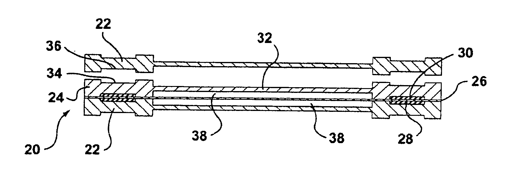
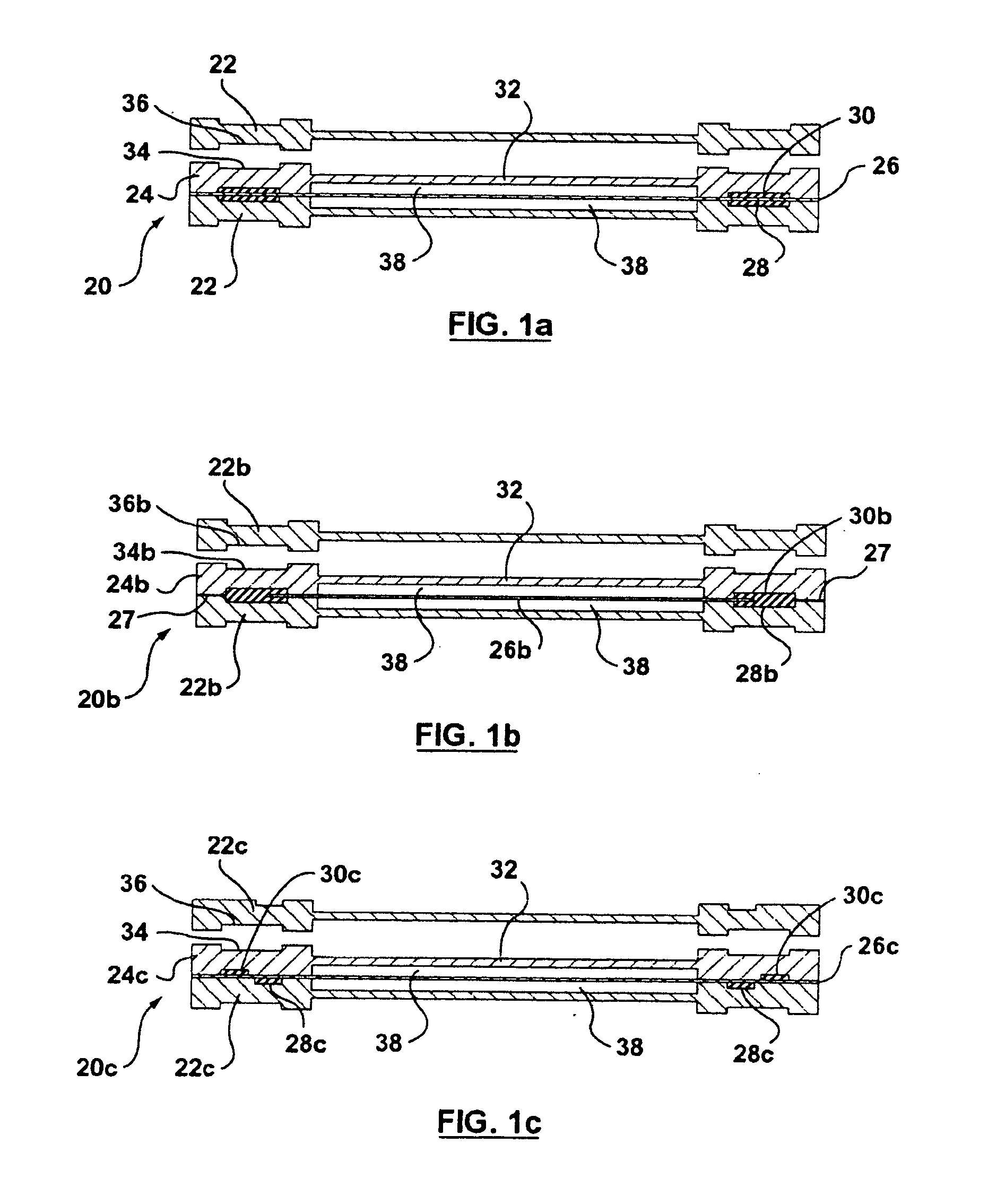
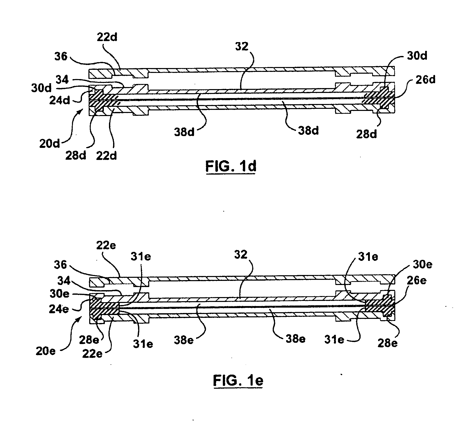
[0104] the earlier invention is shown in FIG. 1a and indicated generally by the reference 20. For simplicity, this Figure shows just part of a fuel cell stack, as does FIG. 2. It will be understood that the other fuel cells in the stack correspond, and that the fuel cell stack would include conventional end elements, clamping elements and the like. In general, FIGS. 1a-3 are intended to indicate the essential elements of the individual embodiments of the invention, and it will be understood by someone skilled in this art that the fuel cell stacks would be otherwise conventional. Also in FIGS. 1a-e and 2, the proton exchange membrane is shown, for clarity, with exaggerated thickness, and as is known, it has a small thickness. In FIGS. 1a-e, the grooves for the seal material are shown schematically, and it is expected that the grooves will usually have a depth and width that are similar, i.e. a generally square cross-section. Note also that the bottom of the grooves can have any desir...

second embodiment

[0112] Now, in accordance with this second embodiment of the present invention, to provide an additional seal and additional security in sealing, a seal-in-place seal 54 is provided around the entire exterior of the fuel cell stack, as indicated. As for FIG. 1a, conventional ports and openings (not shown) would be provided for flow of gases and coolant to the fuel cell stack. To form this seal, the entire stack would be enclosed and ports and vents are provided to enable seal material to be injected to form the outer seal 54 and all the inner seals simultaneously. For this purpose, communication channels and ducts are provided between the grooves for the seals 52 and the exterior of stack where the seal 54 is formed. As before, once the material has been injected, it is cured at room (ambient) temperature or by heating at an elevated temperature. The final seal material on the surface of the stack will serve two purposes, namely to seal the entire stack, and to electrically insulate...


PUM

PropertyMeasurementUnit
Fractionaaaaaaaaaa
Timeaaaaaaaaaa
Angleaaaaaaaaaa

Abstract

A sealing and repair technique is provided for forming complex and multiple seal configurations for fuel cells and other electrochemical cells. To provide a seal, for sealing chambers for oxidant, fuel and/or coolant, a groove network is provided extending through the various elements of the fuel cell assembly. A source of seal material is then connected to an external filling port and injected into the groove network, and the seal material is then cured to form the seal. There is thus formed a “seal in place”, that is robust and can accommodate variations in tolerances and dimensions, and that can be bonded, where possible, to individual elements of the fuel cell assembly. To repair part of an electrochemical cell stack, some elements are removed and either repaired or replaced. The cell assembly is then put together again and a bore is provided for injection of fresh seal material. This bore can either have been formed in the original assembly or is formed by mechanical removal of part of the original seal material

Description

FIELD OF THE INVENTION [0001] This invention relates to electrochemical cells, and this invention more particularly is concerned with an apparatus and a method of forming seals between different elements of a conventional fuel cell or other electrochemical cell stack assembly, to prevent leakage of gases and liquids required for operation of the individual cells. The invention also relates to a method of forming seals with a novel seal material. BACKGROUND OF THE INVENTION [0002] There are various known types of fuel cells. One form of fuel cell that is currently believed to be practical for usage in many applications is a fuel cell employing a proton exchange membrane (PEM). A PEM fuel cell enables a simple, compact fuel cell to be designed, which is robust, which can be operated at temperatures not too different from ambient temperatures and which does not have complex requirements with respect to fuel, oxidant and coolant supplies. [0003] Conventional fuel cells generate relative...

Claims


Application Information

Patent Timeline
IPC IPC(8): H01M2/08H01M8/24B05D5/12
CPCF16J15/14H01M8/008H01M8/0247H01M8/0258Y10T29/4911H01M8/0286H01M8/04089H01M2008/1095Y02E60/50H01M8/0273H01M8/0267H01M8/2483Y02W30/84H01M8/0271
Inventor FRAGIADAKIS, NICKCANDIDO, RAYMONDFROST, H. SAMUEL
Owner HYDROGENICS CORP
Why Eureka
Try Eureka