Rotor cooling system for synchronous machines with conductive sleeve

Active Publication Date: 2007-04-24
HAMILTON SUNDSTRAND CORP
View PDF26 Cites 106 Cited by
  • Summary
  • Abstract
  • Description
  • Claims
  • Application Information

AI Technical Summary

Benefits of technology

[0005]A wound field synchronous machine according to the present invention includes direct oil cooling through a rotor core adjacent a conductive sleeve with elongated semi-arcuate shaped channels which alternate with damper bar channels that contain tie-rod supports structures. The directly cooled conductive sleeve operates at a lower temperature than that of conventional construction. The direct oil cooling minimize localized hot spots and permits the sleeve to be designed for a lower operating temperature. Since the yield strength of the sleeve increases as the max temperature decreases, the lower operating temperatu

Problems solved by technology

However, electrical losses may be present in the conductive sleeve due to the changing magnetic field.
These losses may cause t

Method used


Image

  • Rotor cooling system for synchronous machines with conductive sleeve
  • Rotor cooling system for synchronous machines with conductive sleeve
  • Rotor cooling system for synchronous machines with conductive sleeve

Examples


Example

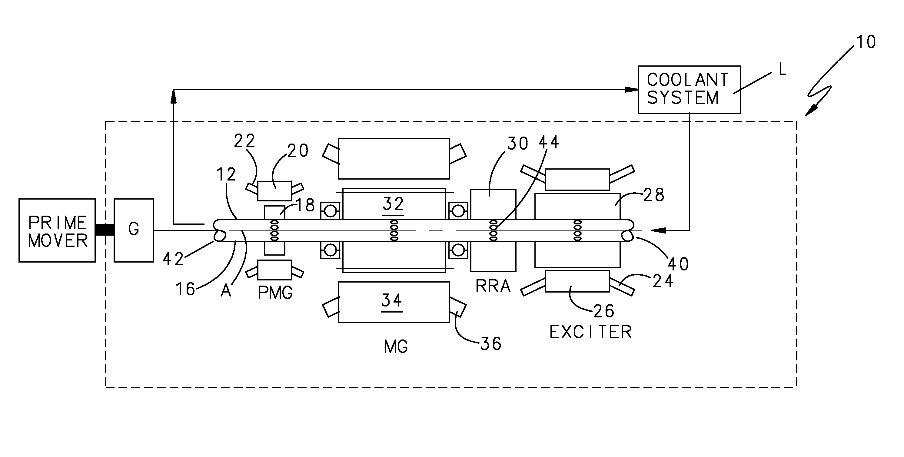
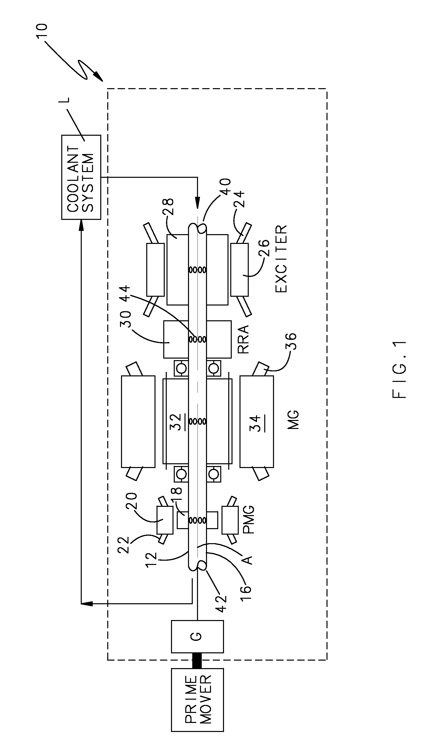
[0022]FIG. 1 illustrates a general schematic block view of a brushless electric generator system 10 that includes a rotor assembly 12 driven about an axis of rotation A by a prime mover such as a gas turbine engine E. It should be understood that although the system is described in terms of a synchronous generator, it may also be utilized as a synchronous motor such as in an aircraft starter generator system. It should also be understood that although a particular component arrangement is disclosed in the illustrated embodiment, other arrangements will benefit from the instant invention.

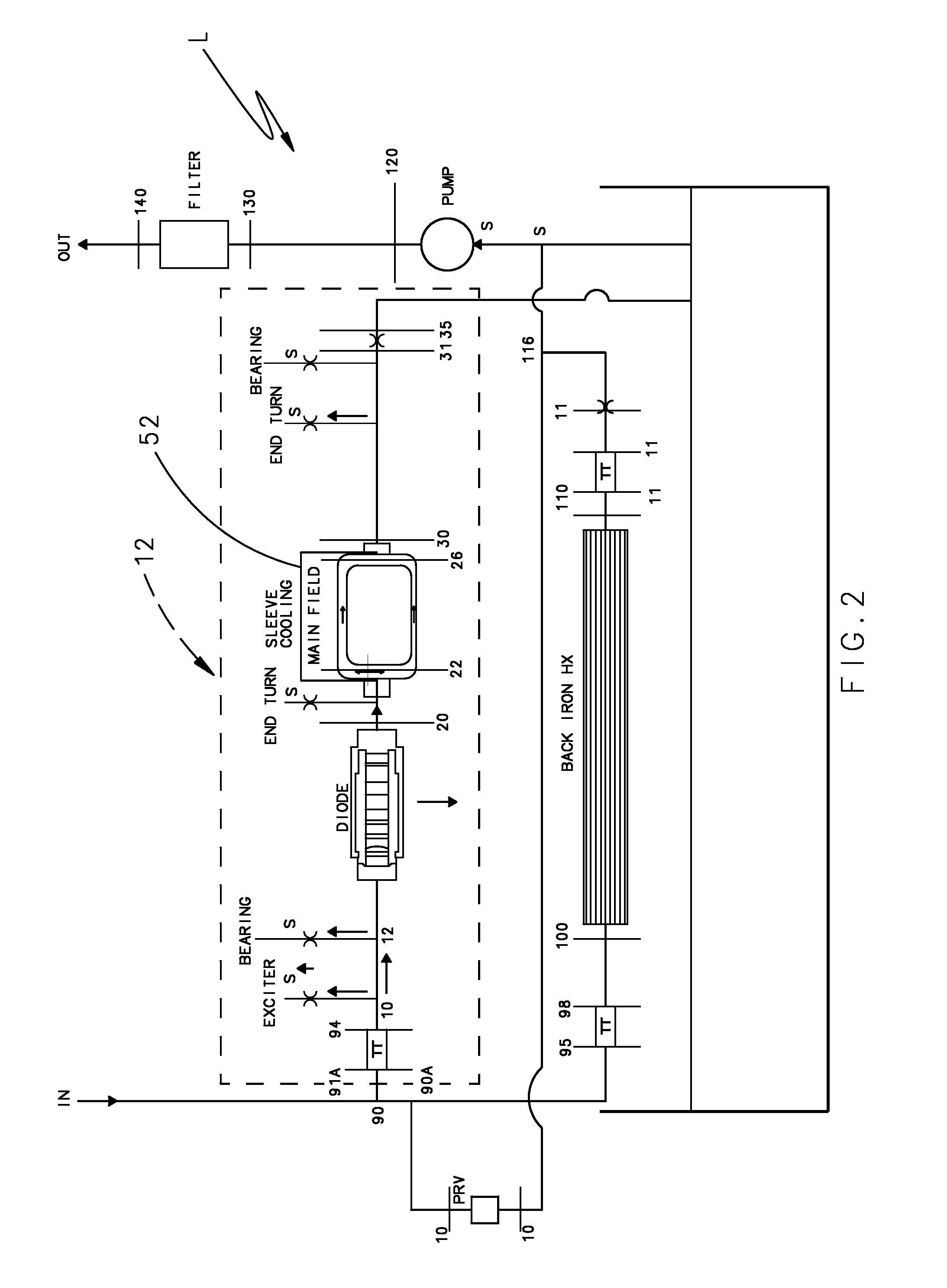
[0023]The generator system 10 preferably includes an integral step-up gearbox G, a lubrication system L (also illustrated schematically in FIG. 2), and a PM generator (PMG) for Generator Control Unit (GCU) power. A Main Generator (MG) is preferably a 170 / 170 kVA two-pole wound field synchronous machine (WFSM) operating nominally at 24000 rpm. Rotor field current is supplied from the output of a rotat...


PUM


Abstract

A wound field synchronous machine includes direct oil cooling along a conductive sleeve with elongated semi-arcuate shaped channels which alternate with damper bar channels containing tie-rod supports structures. With a reduction in sleeve thickness permitted by the direct cooling, the overall weight of the machine is reduced.

Description

BACKGROUND OF THE INVENTION[0001]The present invention relates to a wound field synchronous machine, and more particularly to a coolant system for a reduced weight electric generator system.[0002]Vehicles, such as aircraft, often utilize an electric generator system to provide electric power. The generators convert mechanical energy from rotation of the engine into electrical energy for the vehicle.[0003]The use of conductive sleeves in wound field synchronous machines is commonplace. In some aerospace applications where weight is a critical feature there may be a desire to also use the sleeve to provide additional stiffness to the rotor structure. However, electrical losses may be present in the conductive sleeve due to the changing magnetic field. These losses may cause the temperature of the sleeve to increase to undesirable levels in particular locations related to the changing magnetic fields. A decrease in sleeve thickness provides a weight reduction, but the reduced thickness...

Claims


Application Information

Patent Timeline
IPC IPC(8): H02K9/00H02K9/19
CPCH02K1/32H02K3/24H02K9/19
Inventor SABAN, DANIEL M.HOOBLER, JEFFREY
Owner HAMILTON SUNDSTRAND CORP
Why Eureka
Try Eureka