Electron-source rod, electron source and electronic device

Inactive Publication Date: 2012-07-05
DENKA CO LTD
View PDF13 Cites 4 Cited by
  • Summary
  • Abstract
  • Description
  • Claims
  • Application Information

AI Technical Summary

Benefits of technology

[0024]An electron source according to the present invention can operate at lower operating temperature for an extended period of time. It can also operate reliably at high angular current density and at high probability for an extended period of time.
[0025]The electronic devi

Problems solved by technology

Although it is effective to decrease the temperature of electron source for reduction of color aberration, the decrease in operati

Method used


Image

  • Electron-source rod, electron source and electronic device
  • Electron-source rod, electron source and electronic device
  • Electron-source rod, electron source and electronic device

Examples


example 1

[0055]Example 1 of the present invention will be described in detail with reference to drawings and tables.

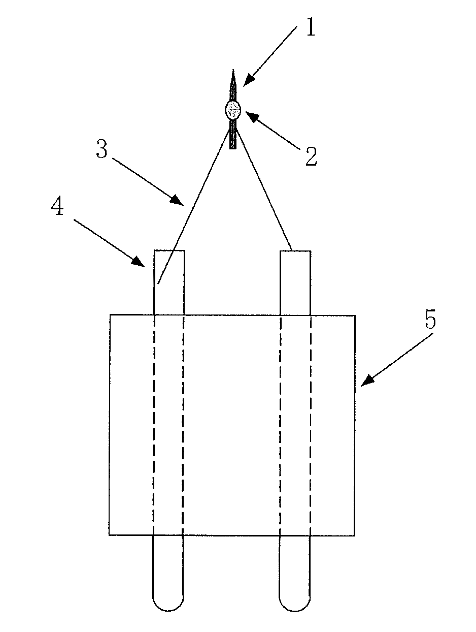
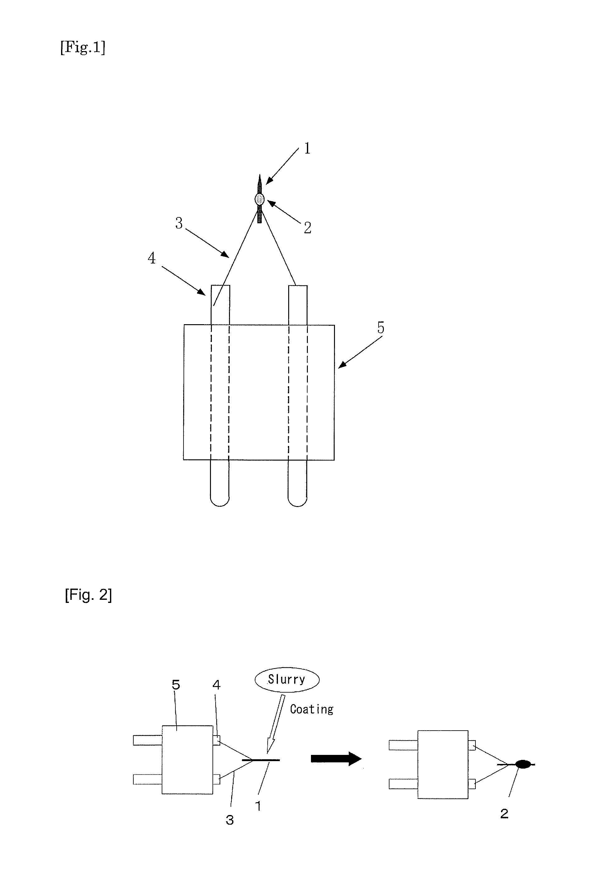
[0056]FIG. 1 is a view illustrating the configuration of the electron source of the present Example. The electron source has an electrical porcelain 5, two conductive terminals 4 connected to the electrical porcelain 5, a filament 3 formed as it is connected to the conductive terminals 4, a rod 1 connected to the filament 3 and a diffusion source 2 formed on the central region of the rod.

[0057]Hereinafter, the method of producing the electron source according to the present invention will be described in detail.

[0058]The rod 1 is made of tungsten single crystal, which has an electron-emitting face exposing the {100} crystal face in the tip region of the rod 1, and the diffusion source 2 is an electron source of a mixed oxide of barium and scandium oxides. The filament 3 is made of tungsten.

[0059]The rod 1 is welded to the filament 3. Both terminals of the filament 3 are fixed ...

examples 2 and 3

[0068]The electron source used in Example 2 was similar to that used in Example 1, except that the materials constituting the diffusion source 2 of Example 1 were used at the rate shown in Table 1. Alternatively, the electron source used in Example 3 is identical with that used in Example 3 in the rate of the constituent materials for the diffusion source 2, but the raw material for the rod was molybdenum.

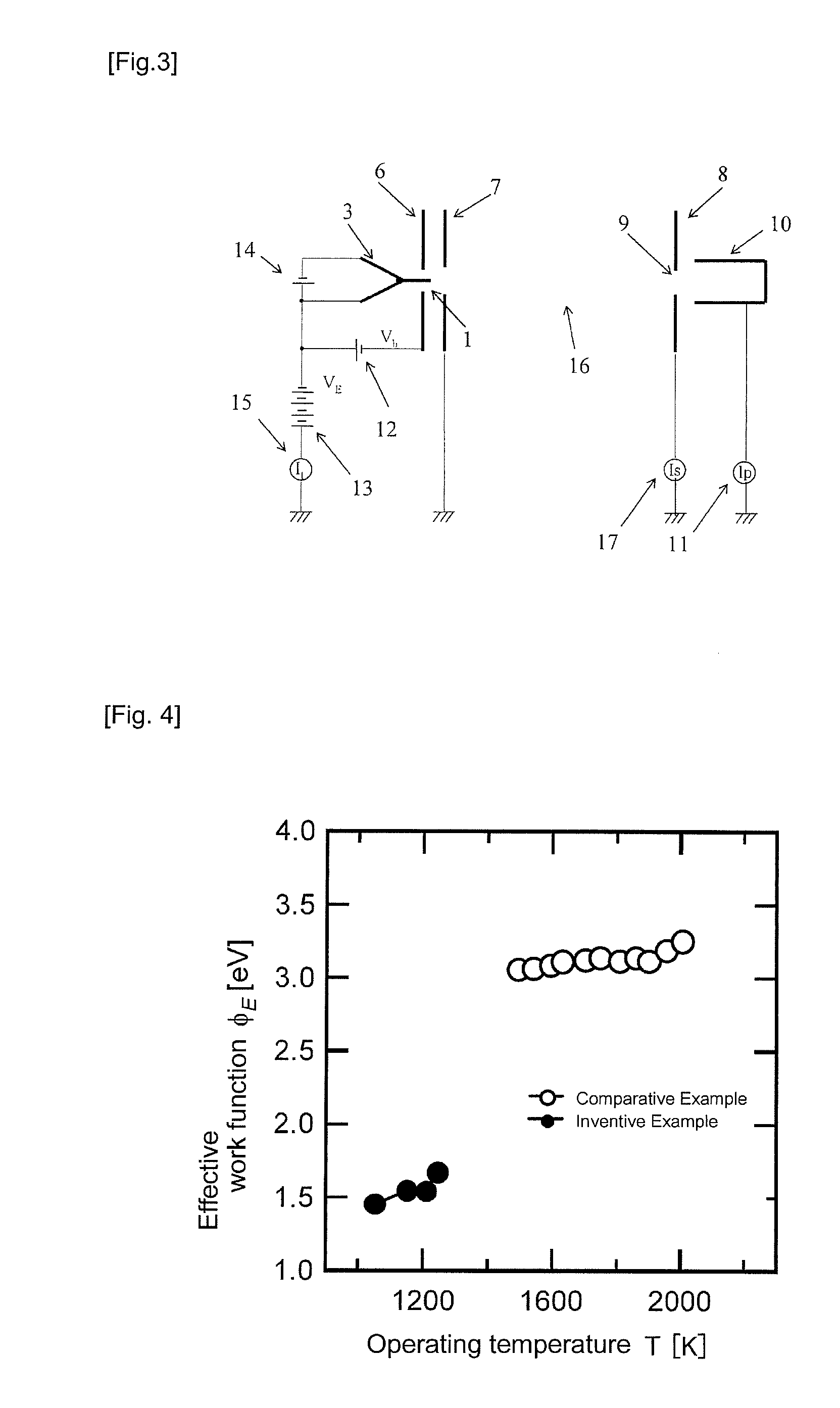
[0069]As shown in Table 1, when the mixed oxide constituting the diffusion source 2 is a mixed barium / scandium oxide at a component ratio of 1:1, the stabilized low-temperature operating range was 900K and the high-temperature operating range was 1250K. The electron emission distribution pattern at the center of the fluorescent plate was analyzed for evaluation of stabilized operating range and the minimum temperature at which the drift of the probe current Ip was 5% or less in 10 hours was used as the stabilized low-temperature operating range, while the maximum temperature as the...

reference examples 1 and 2

[0074]Table 1 shows the operating temperature and operating time of a barium-aluminate described in Patent Document 1 (Japanese Unexamined Patent Application Publication No. 2005-24515) (Example 3: negative voltage applied) as Reference Example 1 and also the stabilized low-temperature and high-temperature regions of Pr2O3 described in Patent Document 2 (Japanese Unexamined Patent Application Publication No. 2008-98087) as Reference Example 2.

[0075]The table shows that the electron sources of Examples 1 to 3 can operate longer than the electron source of Reference Example 1. It also shows that it can operate at an operating temperature lower than that of Reference Example 2. Thus, the electron sources of Examples 1 to 3 are favorable electron sources that can operate at lower operating temperature for an extended period of time.

[0076]The method used for determining the effective work function will be described below.

[0077]The diameter of the {100} crystal face formed on the tip of r...


PUM


Abstract

An electron source is provided that operates at lower temperature and has a low work function and a narrower energy width. The electron source includes a porcelain insulator, two conductive terminals connected to the porcelain insulator, a filament formed between the conductive terminals, and a <100> orientation single crystal rod of at least one metal selected from the group consisting of tungsten, molybdenum, tantalum and rhenium connected to the filament. The rod has an electron-emitting face formed in at its tip region with its {100} crystal face exposed. The rod further includes a diffusion source in its central region that is made of a composite oxide formed from barium oxide and scandium oxide wherein the proportion of barium oxide being 50 mol % or more of BaO and the proportion of scandium oxide being 10 to 50 mol % as Sc2O3 when the mixed oxide is prepared.

Description

TECHNICAL FIELD[0001]The present invention relates to an electron source emitting electron beam, an electron-source rod connected thereto, and an electronic device using the electron source.BACKGROUND ART[0002]Schottky electron emission sources using a needle-shaped electrode of tungsten single crystal have been used recently for emission of an electron beam that has a longer life and is brighter than that from hot cathodes. The electron source, which has a single-crystal tungsten rod with its <100> direction in parallel with the axial direction and a coating layer of zirconium and oxygen (hereinafter, referred to as ZrO coating layer) formed thereon, the ZrO coating layer reducing the work function of the tungsten {100} single crystal from 4.5 eV to approximately 2.8 eV, is characteristic in that the electron beam obtained is brighter and longer-lasting than conventional hot cathodes, because only the microcrystal face corresponding to the (100) face formed on the sharpened t...

Claims


Application Information

Patent Timeline
IPC IPC(8): H01J1/144
CPCH01J1/14H01J2237/06316H01J37/073H01J1/3044
Inventor MORISHITA, TOSHIYUKI
Owner DENKA CO LTD
Why Eureka
Try Eureka