
Apparatus and method for predictive control of a power generation system

a technology of power generation system and predictive control, applied in the direction of electric controllers, ignition automatic control, instruments, etc., can solve the problems of transmission and load equipment damage, and inability to maintain perfect generation and load balance, etc., to achieve the effect of reducing risk

Active Publication Date: 2007-09-13
SIEMENS AG
View PDF7 Cites 154 Cited by
  • Summary
  • Abstract
  • Description
  • Claims
  • Application Information

AI Technical Summary

Benefits of technology

[0017]There is a need for a method and system that reduces the risk of non-compliance wi...

Problems solved by technology

Although it is impossible to maintain a perfect generation and load balance, active control systems attempt to do this by constantly adjusting the power output of the generators.
In addition to load imbalance, system frequency deviations from 60 Hz may also be caused by generators that are not properly meeting their desired generation targets, leading to over-generation or under-generation.
Large frequency deviations from the nominal 60 Hz (e.g., 0.1 Hz), such as caused by the sudden loss of a generator can damage generation, transmission and load equipment, degrade product quality (causing lights to flicker, for example), collapse the power system (by triggering protective system actions, for example) and overload transmission lines as the remaining generators supply additional electricity to those lines in an attempt to restore the system frequency.
Although the power system is designed to quickly recover from the loss of a generator, recovery typically takes several minutes.
Use of the ACE spreads the economic burden of frequency control to all participating generators in all control areas.
Generating an amount of electricity that is in exact equilibrium with the load is extremely difficult and impractical.
Over generation at such times, however, tends to worsen the CPS1 value.

Method used


Image

  • Apparatus and method for predictive control of a power generation system
  • Apparatus and method for predictive control of a power generation system
  • Apparatus and method for predictive control of a power generation system

Examples


Embodiment Construction

[0023]Before describing in detail the methods and apparatuses related to predictive control of a power generation system, it should be observed that the present invention resides primarily in a novel and non-obvious combination of elements and process steps. So as not to obscure the disclosure with details that will be readily apparent to those skilled in the art, certain conventional elements and steps have been presented with lesser detail, while the drawings and the specification describe in greater detail other elements and steps pertinent to understanding the invention.

[0024]The following embodiments are not intended to define limits as to the structure or method of the invention, but only to provide exemplary constructions The embodiments are permissive rather than mandatory and illustrative rather than exhaustive.

[0025]System operators (ISOs) are challenged to readily match changes in load requirements with power generation for their control areas. Currently, ISOs operate the...


PUM


Abstract

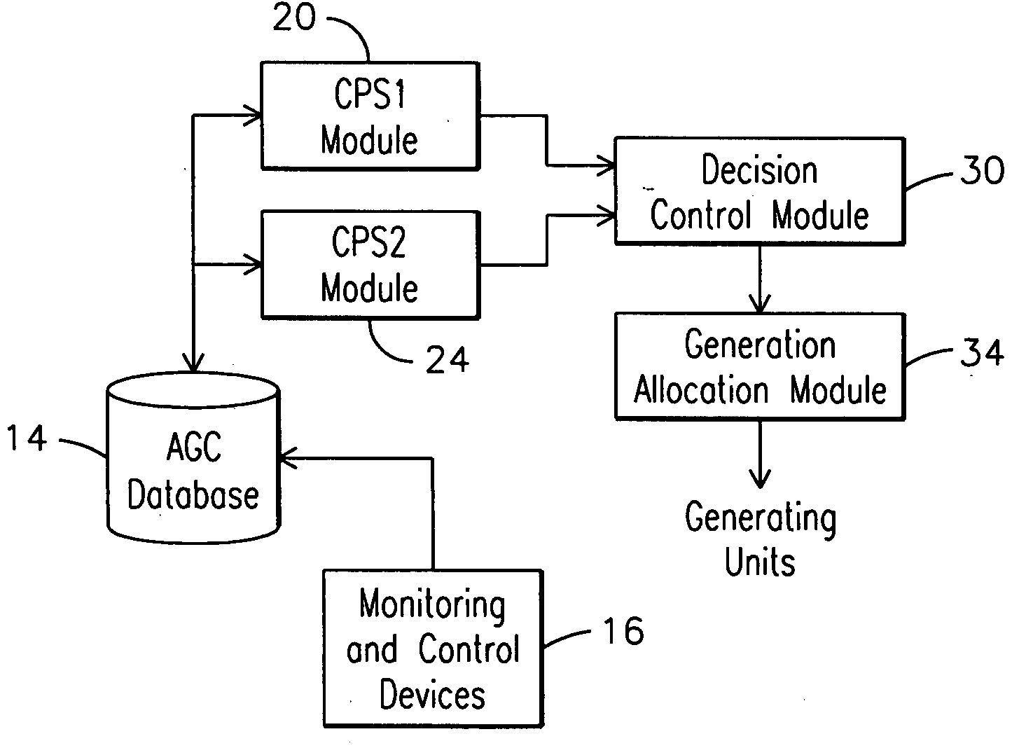
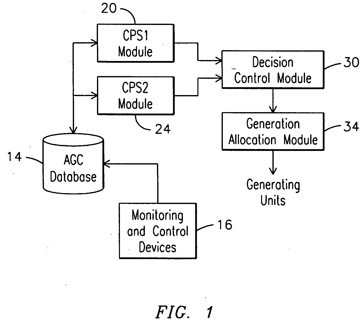
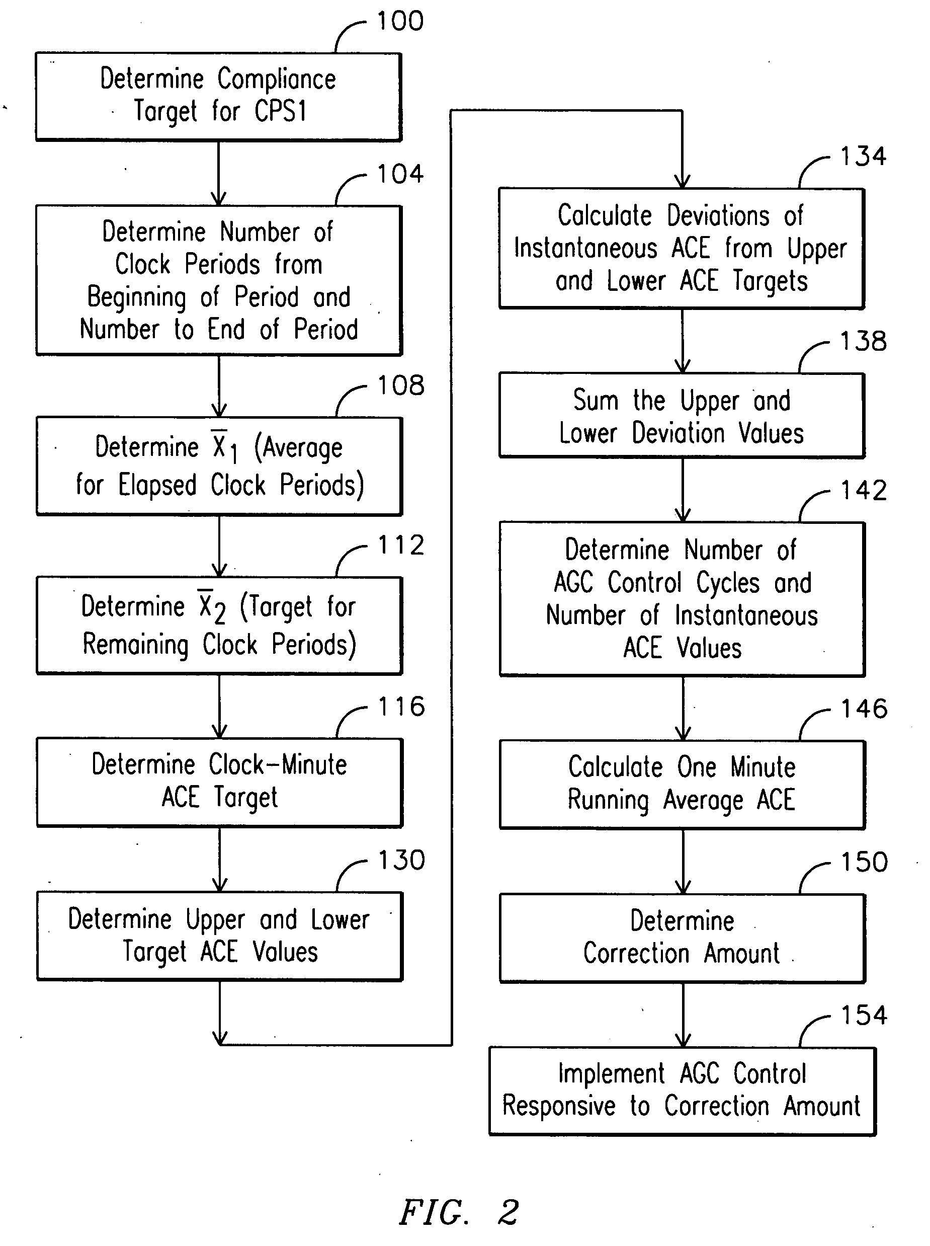
A method for controlling a power system control area according to a first and a second control performance standard, wherein operation of the control area determines area control parameter values. The method comprises (a) determining a first compliance target for the first performance standard and a second compliance target for the second performance standard (100 / 200); (b) determining a first performance standard statistical measure responsive to the control area parameter values from a beginning of a first compliance period to a time at which the first average is determined (108); (c) determining a second performance standard statistical measure responsive to the control area parameter values from a beginning of a second compliance period to a time at which the second average is determined; (d) determining a first area control parameter target responsive to the first performance standard statistical measure (116); (e) determining a second area control parameter target responsive to the second performance standard statistical measure (204); (f) determining a first area control parameter correction responsive to the first area control parameter target and the area control parameter values (150); (g) determining a second area control parameter correction responsive to the second area control parameter target and the area control parameter values (228) and (h) controlling the power system according to one or both of the first and the second area control parameter corrections (154 / 232).

Description

[0001]The present application claims the benefit under Section 119(e) of the provisional patent application filed on Mar. 8, 2006 and assigned application No. 60 / 780,136, and also of the provisional patent application filed on Mar. 7, 2006 and assigned application No. 60 / 779,845.FIELD OF THE INVENTION[0002]The present invention relates generally to control of a power generation / load management system and more specifically to predictive control of the power generation / load management system responsive to certain control performance standards.BACKGROUND OF THE INVENTION[0003]The electrical power system (grid) includes generating sites, transmission lines, distribution equipment and end uses (loads). The electricity is generated competitively at multiple power plants and transmitted from the generating sites over the transmission lines regulated by the Federal Energy Regulatory Commission (FERC). Generation and transmission of the electricity are usually managed and controlled by regio...

Claims


Application Information

Patent Timeline
IPC IPC(8): G05D11/00
CPCH02J3/00H02J2203/20Y02E60/00Y04S40/20
Inventor CHEN, DINGGUO
Owner SIEMENS AG
Learn More