Liquid-droplet jetting head and liquid-droplet jetting apparatus

a technology of liquid droplet and jetting head, which is applied in the direction of printing, etc., can solve the problems of increasing the cost of the driver chip and the power supply, and the gain of the driver chip, so as to improve the performance of the piezoelectric transformer, increase the signal amplification factor, and increase the gain

Active Publication Date: 2007-09-20
BROTHER KOGYO KK
View PDF1 Cites 28 Cited by
  • Summary
  • Abstract
  • Description
  • Claims
  • Application Information

AI Technical Summary

Benefits of technology

[0036]In this case, it is possible to raise a gain (step-up ratio) according to the number of stacked layers.
[0037]In the liquid-droplet jetting head of the present invention, a recess may be formed in areas of the channel unit and the vibration plate respectively, each of the areas overlapping with the second portion. In this case, since a deformation of the second portion is not obstructed (not inhibited), it is possible to improve a performance as the piezoelectric transformer, and to increase a signal amplification factor of the second portion.
[0038]In the liquid-droplet jetting head of the present invention, the second portion may include a plurality of transformer portions arranged in a row, and a recess may be formed in areas, of the second portion,

Problems solved by technology

In a liquid droplet jetting head such as the ink-jet head described above, when the drive voltage is increased, it leads to a rise in a cost of the d

Method used


Image

  • Liquid-droplet jetting head and liquid-droplet jetting apparatus
  • Liquid-droplet jetting head and liquid-droplet jetting apparatus
  • Liquid-droplet jetting head and liquid-droplet jetting apparatus

Examples


Embodiment Construction

[0058]An embodiment of the present invention will be described below with reference to the diagrams.

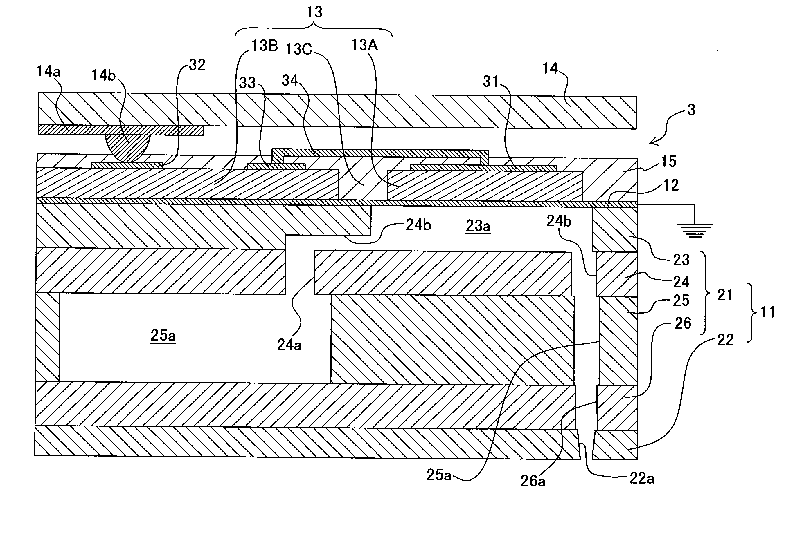
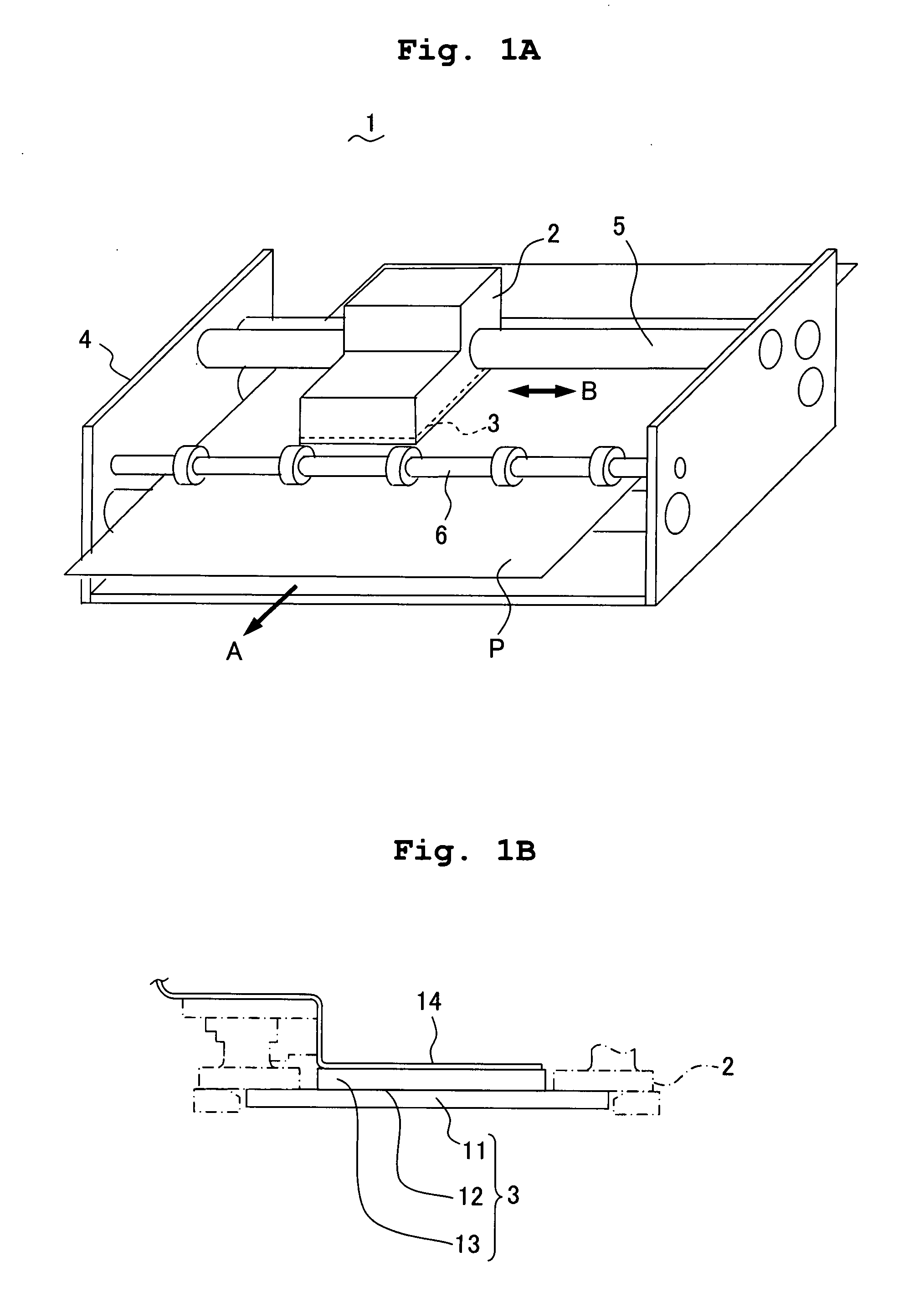
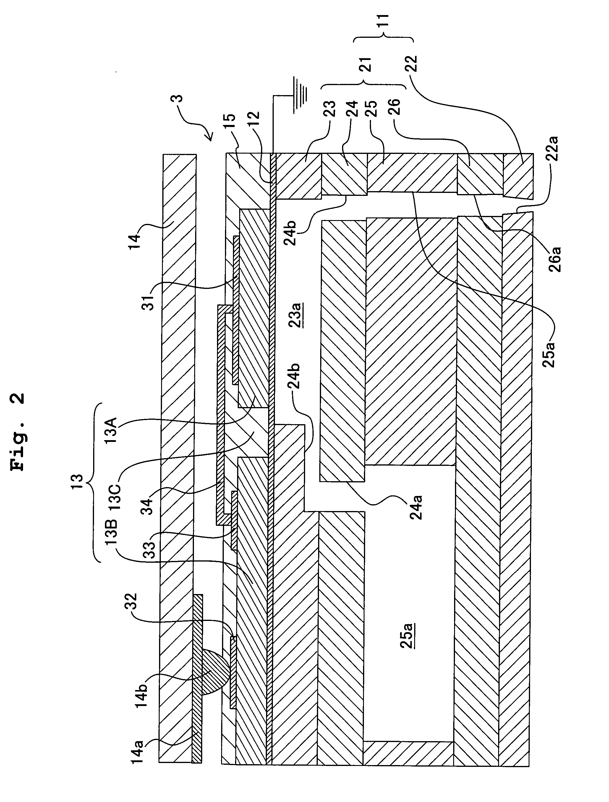
[0059]FIG. 1A is a schematic structural view showing a schematic structure of an ink-jet printer according to the present invention, and FIG. 1B is a diagram showing a relationship between a piezoelectric material layer and a flexible flat cable.

[0060]As shown in FIG. 1A, an ink-jet printer as an example of a liquid-droplet jetting apparatus according to the present invention is provided with an ink-jet head 3 on a lower surface of a carriage 2 on which an ink cartridge (not shown) is mounted, which records an image on to a recording paper P (recording medium). The carriage 2 is supported by a guide plate (not shown) and a carriage shaft 5 provided in a printer frame 4, and reciprocates in a direction (direction B in FIG. 1A) which is orthogonal to a direction of transporting of the recording paper P (direction A in FIG. 1A).

[0061]The recording paper P which is carried in the directio...


PUM


Abstract

An ink-jet head includes a channel unit which includes a plurality of pressure chambers, a vibration plate stacked on the channel unit, and a piezoelectric material layer arranged on the vibration plate. The piezoelectric material layer includes a first portion functioning as a piezoelectric actuator, and a second portion functioning as a piezoelectric transformer which amplifies a driving signal to be supplied to the piezoelectric actuator. Accordingly, it is possible to realize a small-size ink-jet head with a built-in piezoelectric amplifier.

Description

CROSS REFERENCE TO RELATED APPLICATION[0001]The present application claims priority from Japanese Patent Application No. 2006-070264, filed on Mar. 15, 2006, the disclosure of which is incorporated herein by reference in its entirety.BACKGROUND OF THE INVENTION[0002]1. Field of the Invention[0003]The present invention relates to a liquid droplet jetting head and a liquid droplet jetting apparatus.[0004]2. Description of the Related Art[0005]In hitherto available liquid droplet jetting heads such as an ink-jet head in which a piezoelectric actuator is used, a driving pulse (such as a driving waveform and a voltage signal) which drives the piezoelectric actuator is generated in a driver chip, and is directly supplied to the piezoelectric actuator which is provided corresponding to a pressure chamber of the ink-jet head.[0006]Taking into consideration a cost aspect, a drive voltage is sought to be lowered. Whereas, since a deformation of the piezoelectric actuator closely depends on th...

Claims


Application Information

Patent Timeline
IPC IPC(8): B41J2/045
CPCB41J2002/14491B41J2/14233
Inventor KOBAYASHI, KAZUOISHIKAWA, HIROYUKI
Owner BROTHER KOGYO KK
Why Eureka
Try Eureka