Time switch

a time switch and schedule technology, applied in the field of time switches, can solve problems such as the difficulty of a user to set up or change the schedule, and achieve the effect of convenient setting up or changing the schedul

Inactive Publication Date: 2007-09-20
MATSUSHITA ELECTRIC WORKS LTD
View PDF9 Cites 22 Cited by
  • Summary
  • Abstract
  • Description
  • Claims
  • Application Information

AI Technical Summary

Benefits of technology

[0009]The present invention has been made to solve the aforementioned problems, and an object of the presen

Problems solved by technology

Accordingly, it was difficult for a u

Method used


Image

  • Time switch
  • Time switch
  • Time switch

Examples


Embodiment Construction

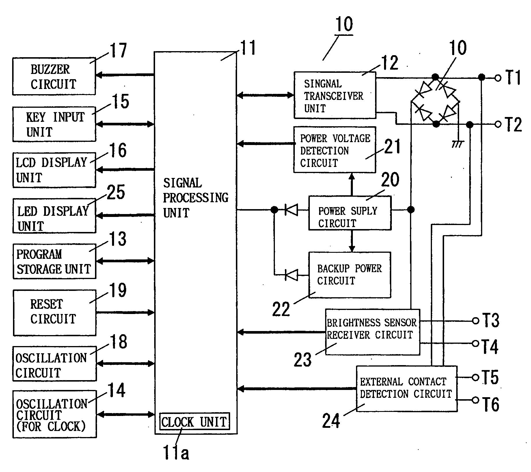
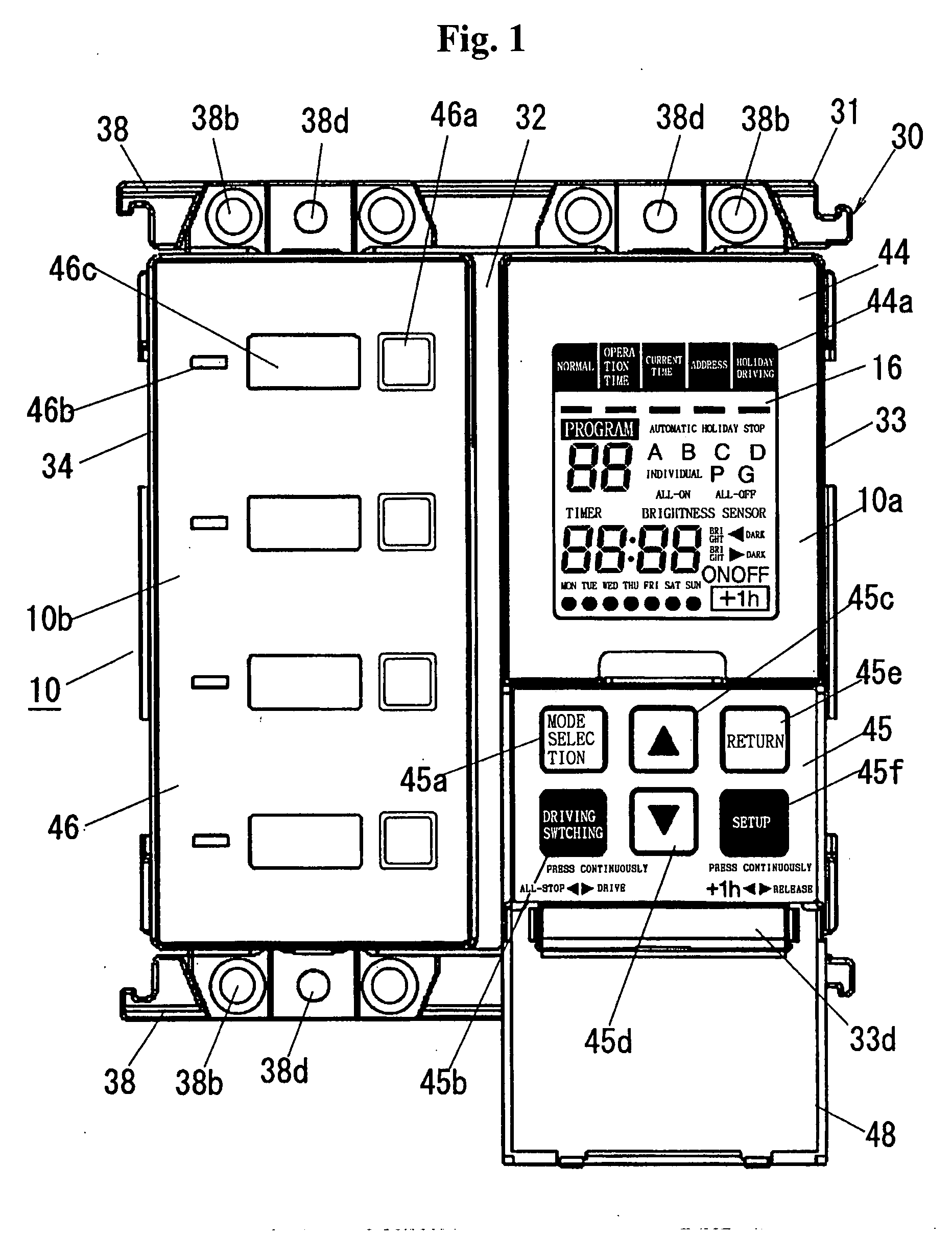
[0025]A time switch which will be described below according to the present embodiment is usually installed in facilities such as typical dwelling units, offices, and schools and performs a timer control for the objective loads on the basis of a predetermined weekly schedule. Needless to say, although control of a lighting load is described as an example in the present embodiment, the load is not limited to the lighting load, but the present embodiment can be applied to any load required to be operated on the basis of a schedule.

[0026]The time switch 10 of the present embodiment is usually connected to a signal line Ls in a remote monitoring control system as shown in FIG. 6. Accordingly, a basic construction of the remote monitoring control system will be described firstly with reference to FIG. 6. In this remote monitoring control system, a relay-attached parent unit (hereinafter, referred to as a parent controller 1), a plurality of (e.g., two in FIG. 5) relay-attached child units...


PUM


Abstract

Provided is a time switch capable of allowing a user to readily set up or change a schedule. For this purpose, a chassis 30 of the time switch 10 has same size (i.e., two-row-module size) as that obtained by arranging two three-module sized implanted type wiring devices in two lines along a minor width direction, and installation frame pieces 38 are protruded from both of upper and lower side walls. In addition, each installation frame piece 38 has a long hole 38a for inserting a box screw fastened to the implanted type box (not shown) implanted on the installation surface or a fastener hole combined with a fastener. Furthermore, decoration covers 33 and 34 are installed in the front side of the chassis 30, and manipulating buttons 45a to 45f of the setup manipulation unit for setting up a time schedule having a set of an address corresponding to the control target load, and a control time and a control item for the load are provided in the decoration cover 33 functioning as a manipulation face of the setup unit 10a.

Description

BACKGROUND OF THE INVENTION[0001]1. Technical Field[0002]The present invention relates to a time switch.[0003]2. Related Art[0004]Conventionally, there has been provided a remote monitoring control system in which a manipulating switch wiring appliance for monitoring switch inputs from a manipulating switches and a remote control wiring appliance for controlling a turning-on / off operation of the corresponding loads are connected to a transmission control device through a double-wire signal line, an individual address is allocated to each wiring appliance, a transmission signal containing the address is transmitted and received between the transmission control device and each wiring appliance using a time division multiplexing transmission scheme.[0005]The transmission control device individually has an access to the manipulating switch wiring appliance and the remote control wiring appliance by transmitting a transmission signal containing address data to the signal line, generates ...

Claims


Application Information

Patent Timeline
IPC IPC(8): H04L12/50
CPCG05B2219/21042H05B37/02G09G3/3406G05B2219/21088H05B47/165H05B47/17H05B47/10H05B47/16
Inventor KAWAMATA, MOTOTSUGU
Owner MATSUSHITA ELECTRIC WORKS LTD
Why Eureka
Try Eureka