Mixing Apparatus

Active Publication Date: 2011-02-03
YAMAHA CORP
View PDF3 Cites 6 Cited by
  • Summary
  • Abstract
  • Description
  • Claims
  • Application Information

AI Technical Summary

Benefits of technology

[0007]In view of the foregoing, it is an object of the present invention to provide an improved mixing apparatus which can readily set signal processing to be performed on a cue signal even if the signal processing is diversified.
[0009]Namely, according to the present invention, one of a plurality of sets of setting information is referenced in accordance with the type of the channel selected in accordance with a cue instruction, and one or more signal processing operations, which are to be performed by the cue signal processing section, are automatically determined in such a manner that each signal processing operation set in an ON state in the set of setting information in correspondence with the type of the selected channel is performed on the signal supplied to the cue bus. Thus, even where the signal processing operations to be performed on the signal supplied to the cue bus are diversified, the present invention can easily set ON or OFF of the individual signal processing operations.

Problems solved by technology

Rather, when the input channel is to be cued, it is desired to monitor a non-delayed real-time cue signal; however, none of the conventionally-known mixing apparatus can monitor such a real-time cue signal because the signal of the input channel to be cued is delayed by the cue function section as noted above.
However, the equalizer in the cue function section is constantly kept operative, and thus, when a signal of a given output channel is to be auditorily monitored on the basis of cue operation, signal processing is performed on a cue signal by both the equalizer inserted in the given output channel and the equalizer inserted in the cue channel; in this case, it is not possible to auditorily check as-is the sound of the given output channel.
However, if the signal processing operations are diversified like this, operation for setting signal processing to be performed in accordance with a category of the cue signal would become very complicated, and thus, the conventionally-known mixing apparatus cannot appropriately deal with the diversification of the signal processing.

Method used


Image

  • Mixing Apparatus
  • Mixing Apparatus
  • Mixing Apparatus

Examples


Embodiment Construction

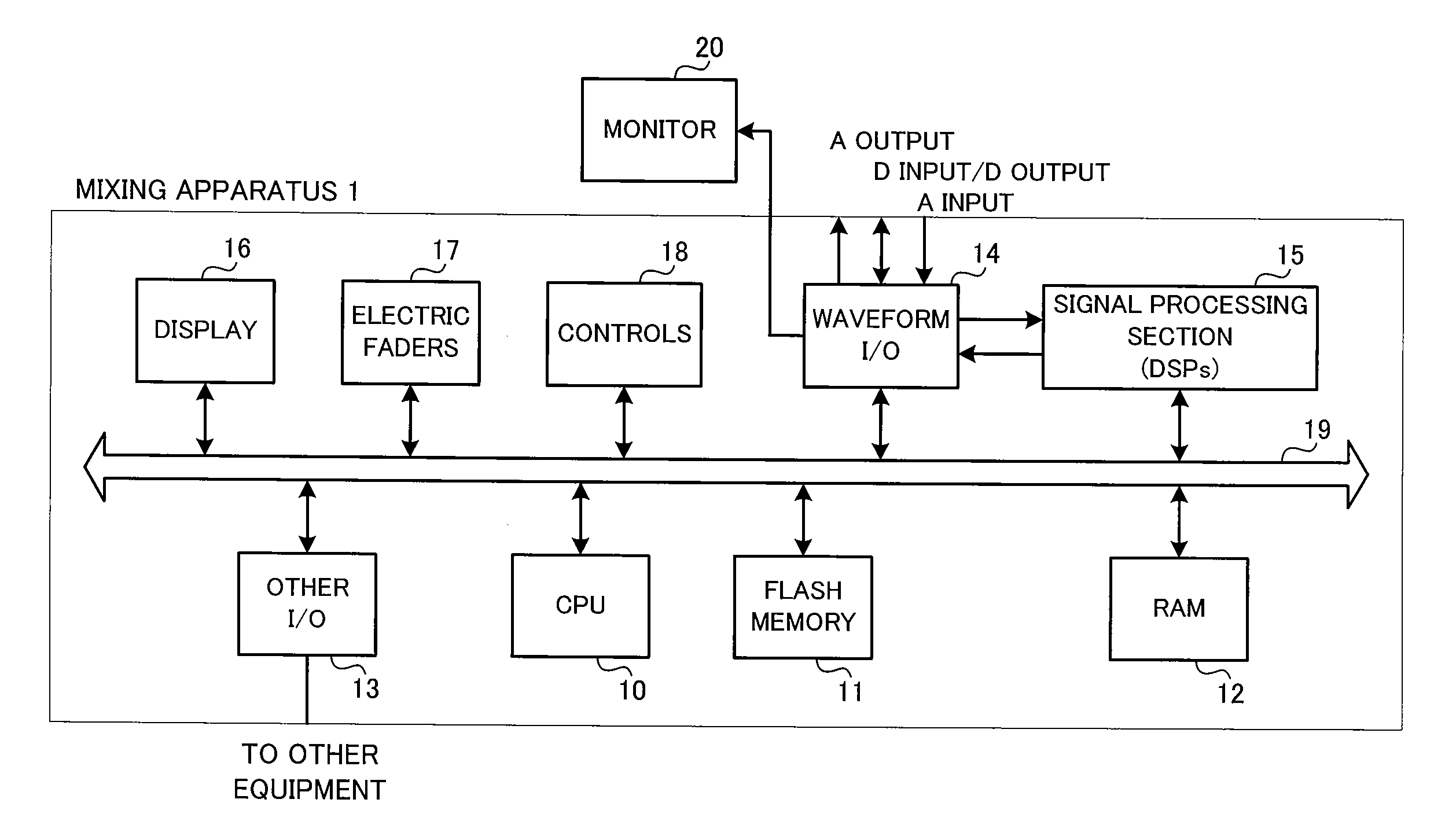
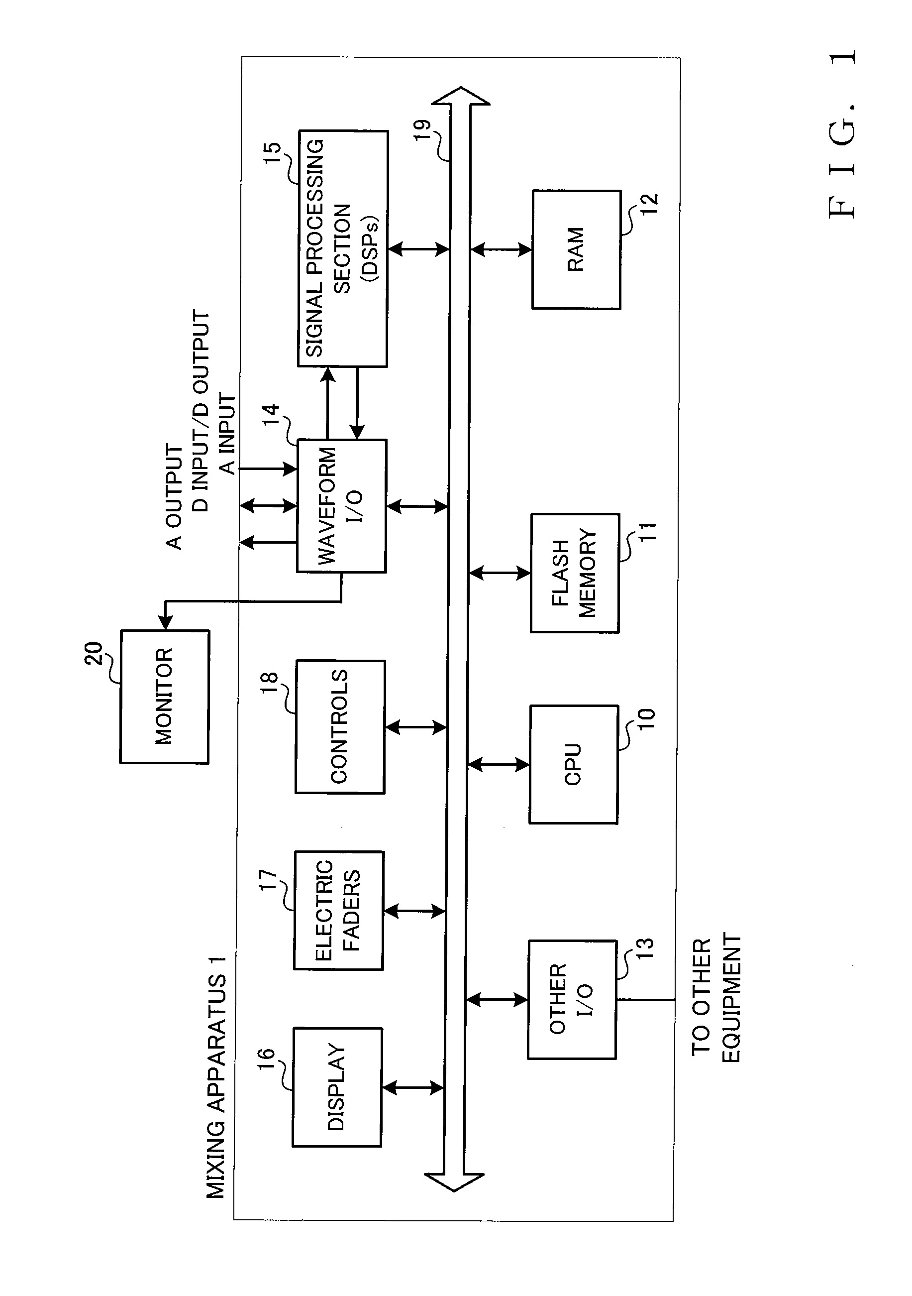
[0028]FIG. 1 is a block diagram showing an example construction of an embodiment of a mixing apparatus of the present invention. The mixing apparatus 1 of FIG. 1 includes a CPU (Central Processing Unit) 10 that not only controls overall operation of the entire mixing apparatus 1 but also generates control signals in response to operation, by a human operator or user, of various mixing controls (operators), a rewritable, non-volatile flash memory 11 having stored therein operating software, such as a mixing control program, which is to be executed by the CPU 10, and a RAM (Random Access Memory) 12 including a working area for the CPU 10 and storing various data etc. By the operating software being stored in the flash memory 11 like this, version upgrade of the operating software can be done. A digital recorder and other devices are connected to the mixing apparatus 1 via an “other I / O”13 that is an input / output interface.

[0029]All input and output to and from the mixing apparatus 1 i...


PUM


Abstract

Signal of a channel selected in accordance with a cue instruction is supplied to a cue bus. Cue signal processing section provided in the cue bus can perform one or more signal processing operations, selected from among a predetermined plurality of different signal processing operations, such as “Delay”, “Insert” and “Equalizer”. For each of a plurality of channel types, a set of setting information is stored which contains information for setting ON or OFF of individual ones of the plurality of different signal processing operations. The set of setting information corresponding to the type of the channel selected via the cue instruction is referenced, and one or more signal processing operations is determined in such a manner that each signal processing operation set in an ON state in the setting file in correspondence with the type of the selected channel is performed on the signal supplied to the cue bus.

Description

BACKGROUND[0001]The present invention relates to a mixing apparatus having a function for performing signal processing operations on a cue signal (i.e., audio signal output from a CUE bus) for auditorily monitoring a signal of a selected section of the mixing apparatus on the basis of cue operation, and a method for setting ON or OFF of the individual signal processing operations in the mixing apparatus.[0002]As one form of audio signal processing apparatus, there have heretofore been known mixing apparatus for use in concerts, events, gatherings, theatrical performances, etc., which are constructed to mix audio signals, output from a multiplicity of microphones, electric and electronic musical instruments, etc. after adjusting levels and frequency characteristics of the audio signals and then output the mixed audio signals to a power amplifier. A human operator, operating such a mixing apparatus, operates various panel controls of the mixing apparatus to adjust volumes and colors o...

Claims


Application Information

Patent Timeline
IPC IPC(8): H04B1/00
CPCH04H60/04
Inventor AOKI, TAKAMITSUOKABAYASHI, MASAAKI
Owner YAMAHA CORP
Why Eureka
Try Eureka