
Spinning camera enclosure for environmental protection

a camera enclosure and environmental protection technology, applied in the field of environmental protection enclosures, can solve the problems of filter cover not preventing water drops from appearing in the lens image, affecting the performance of the lens outdoors, and affecting the image quality of the lens

Active Publication Date: 2007-09-20
IMMERSIVE LICENSING
View PDF5 Cites 63 Cited by
  • Summary
  • Abstract
  • Description
  • Claims
  • Application Information

AI Technical Summary

Benefits of technology

[0002] Many environmental factors can diminish the performance of a lens outdoors. Rain, mist, soot and dust all cause the image to become clouded as the clear parts of the lens are covered up. Because water and dirt also can harm the special coatings on the front surfaces of lenses, it is common practice to cover and protect the front elements of lenses with a clear or UV-blocking glass filter, held in place in front of the lens by a screw-threaded enclosure. But this type of filter cover does not prevent water drops from appearing in the lens image in the rain, or dust from clouding the image in a dust storm. To try to prevent this, the camera can be swathed in a hooded waterproof wrapping, with the lens looking out of a tunnel or awning that helps keep out the rain and dust, but which is not visible within the field of view of the lens. However, this does not entirely protect the lens, especially when the lens is pointed up at the rain, and raindrops can sometimes be seen dripping from the forward edge of the tunnel. The camera operator must always be alert and ready to wipe the lens clear if necessary. And when the lens is a wide-angle lens, the tunnel cannot be long enough to protect the lens and still remain invisible.
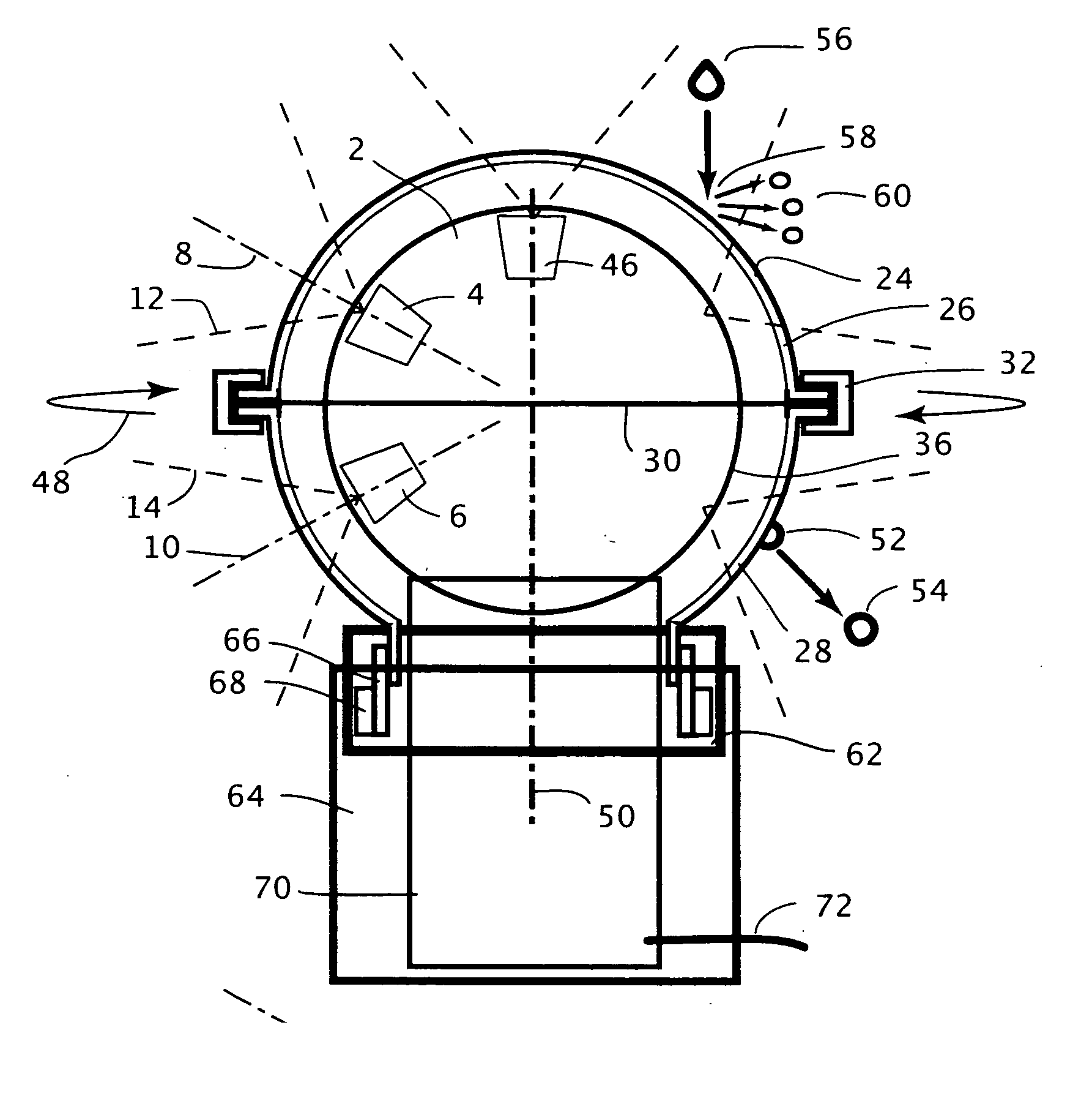
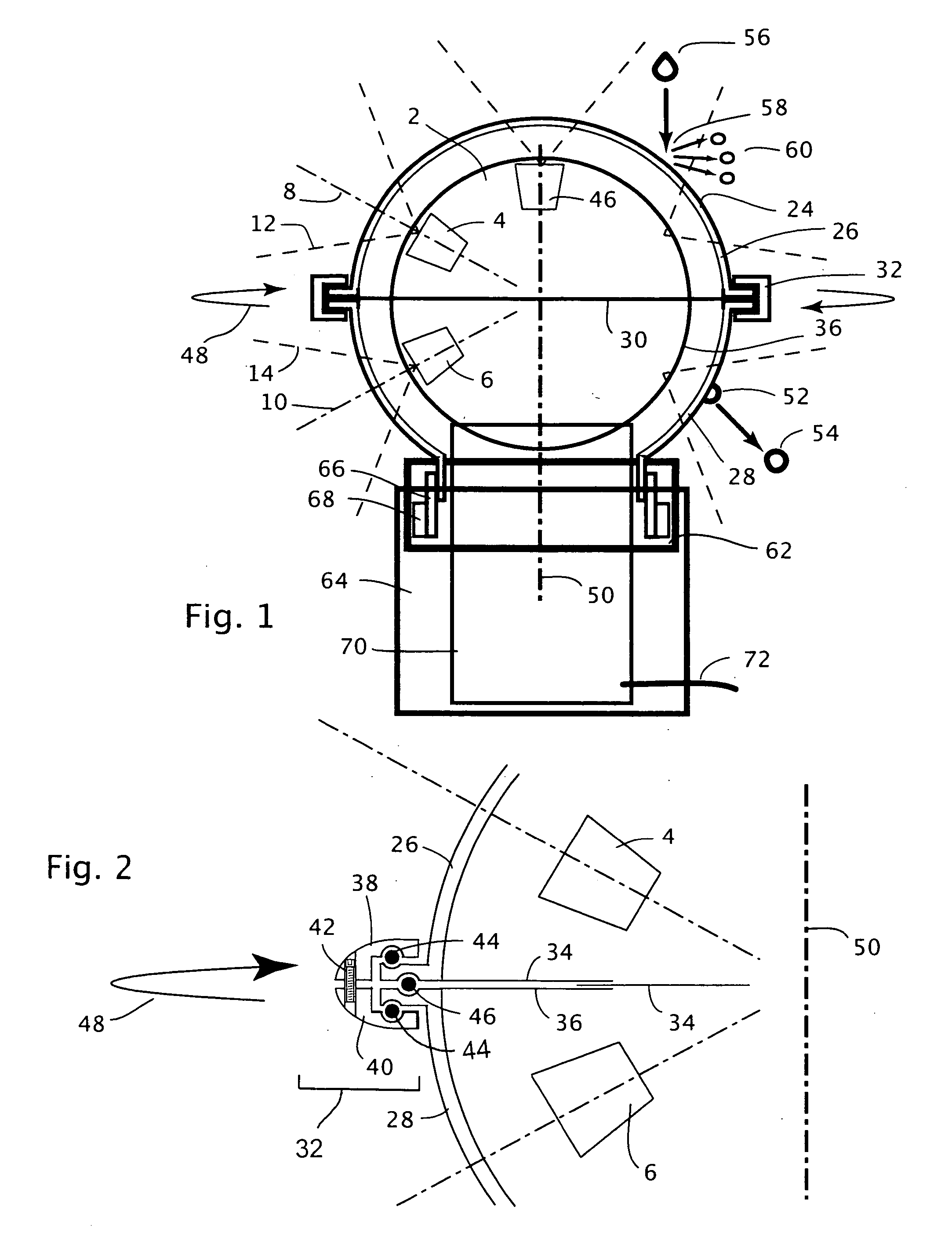
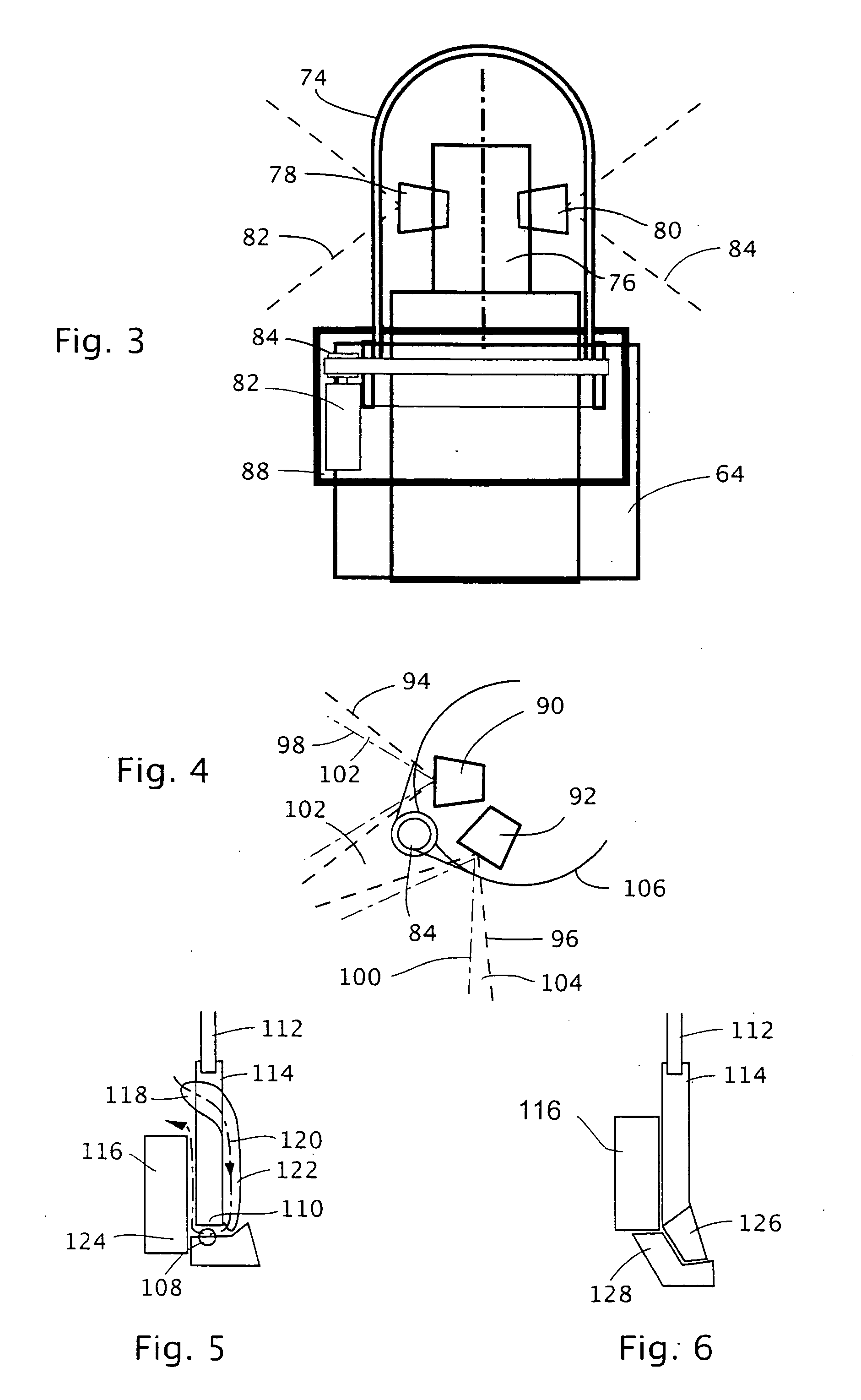
[0005] The present invention changes the approach to lens protection to include wide-angle and even immersive camera systems, by the use of a specially designed, rapidly spinning clear volumetric enclosure or “shell.” Unlike conventional lens filters, the present invention does not allow the buildup of any raindrops or dust to cloud the lens image. The present invention provides environmental protection from a wide variety of hazards and maintains a clear lens image automatically, without user intervention, and is invisible to camera systems with single or multiple panoramic or immersive camera lenses. In addition, the mechanical rotation of the present invention provides camera stabilization through gyroscopic action, and also the means to cool the camera by blowing air through the protected enclosed space.

Problems solved by technology

Many environmental factors can diminish the performance of a lens outdoors.
Rain, mist, soot and dust all cause the image to become clouded as the clear parts of the lens are covered up.
Because water and dirt also can harm the special coatings on the front surfaces of lenses, it is common practice to cover and protect the front elements of lenses with a clear or UV-blocking glass filter, held in place in front of the lens by a screw-threaded enclosure.
But this type of filter cover does not prevent water drops from appearing in the lens image in the rain, or dust from clouding the image in a dust storm.
However, this does not entirely protect the lens, especially when the lens is pointed up at the rain, and raindrops can sometimes be seen dripping from the forward edge of the tunnel.
And when the lens is a wide-angle lens, the tunnel cannot be long enough to protect the lens and still remain invisible.
As camera systems have evolved to include panoramic and immersive cameras, with lenses that in some cases face in many directions at once, the problem has increased.
However, this device has a large frame and motor assembly for spinning the disk, and is designed to be used with a single lens that has a relatively narrow field of view.
Because of this, it cannot be used for protecting immersive or panoramic cameras, which often have multiple lenses that look in several directions and would always see such a bulky spinning disk mechanism.

Method used


Image

  • Spinning camera enclosure for environmental protection
  • Spinning camera enclosure for environmental protection
  • Spinning camera enclosure for environmental protection

Examples


Embodiment Construction

[0013] In the discussion that follows, terms such as “water,”“lens” and “camera” are used to describe the function and operation of the present invention and an exemplary type of sensor that could make use of the invention. No particular limitation should be inferred from these terms; they are used as general descriptors for environmental protection.

[0014] The present invention features a rapidly-spinning clear volumetric enclosure or “shell” for a camera system or other type of sensor. The lens or lenses of this camera system look out from within the shell, and the shell and the motor that spins it are designed to be essentially invisible to the camera system. As the shell spins, a constant distance is maintained between the shell and the camera lens or lenses, and any water drops or dust particles that contact the shell surface are quickly thrown off it by a combination of the fast relative motion of the shell, the local air currents at the surface of the shell, and centrifugal f...


PUM


Abstract

An environmental protection system features a clear spinning curved volumetric enclosure to shed and throw off environmental contaminants such as rain, fog and dust that would affect a sensor image. The described design is especially suitable for cameras with extremely wide fields of view, such as panoramic or immersive cameras. Alternate forms of volumetric enclosures are described for different lens arrangements in compound camera systems. In all of these embodiments it is possible to keep the cover and the mechanism spinning it invisible to the cameras. An additional modification of the shape of the volumetric enclosure is described that prevents any accumulation of liquid drops within the fields of view of the sensors within the spinning volumetric enclosure. Alternate forms of construction with air and magnetic bearings are described for smoother and quieter operation of the spinning enclosure.

Description

FIELD OF THE INVENTION [0001] This invention generally relates to environmental protection enclosures, and specifically lens protection for camera systems. BACKGROUND AND SUMMARY OF THE INVENTION [0002] Many environmental factors can diminish the performance of a lens outdoors. Rain, mist, soot and dust all cause the image to become clouded as the clear parts of the lens are covered up. Because water and dirt also can harm the special coatings on the front surfaces of lenses, it is common practice to cover and protect the front elements of lenses with a clear or UV-blocking glass filter, held in place in front of the lens by a screw-threaded enclosure. But this type of filter cover does not prevent water drops from appearing in the lens image in the rain, or dust from clouding the image in a dust storm. To try to prevent this, the camera can be swathed in a hooded waterproof wrapping, with the lens looking out of a tunnel or awning that helps keep out the rain and dust, but which is...

Claims


Application Information

Patent Timeline
IPC IPC(8): G03B17/00
CPCG03B17/00G08B13/1963G08B13/19619G03B17/08G02B27/0006
Inventor MCCUTCHEN, DAVIDADKINS, CRAIG
Owner IMMERSIVE LICENSING
Learn More