Air collector with functionalized ion exchange membrane for capturing ambient co2

a technology of air collector and ion exchange membrane, which is applied in the field of air collector with functionalized ion exchange membrane for capturing ambient co2, can solve the problems of large-scale hydrocarbon-fueled power plants that are not fully protected from exhausting co2 into the atmosphere, large-scale emitters that are impractical to mitigate at the source, and the need to reduce co2 emissions from all sources. , to achieve the effect of repeatable air capture performance and low energy needs

Active Publication Date: 2007-09-20
CARBON SINK
View PDF56 Cites 63 Cited by
  • Summary
  • Abstract
  • Description
  • Claims
  • Application Information

AI Technical Summary

Benefits of technology

[0012] In our co-pending PCT Application Serial No. PCT / US06 / 029238, filed Jul. 28, 2006, we describe specific requirements for the chemical performance of the solid phase ion exchange material. This application in one aspect addresses mechanical configurations and air-side performance enhancements to ensure that the low energy needs of the overall system are met while ensuring a robust design with repeatable air capture performance. In another aspect, this application describes an integrated system for reforming CO2 into other molecules that will permanently prevent the reintroduction of the captured CO2 into the atmosphere.

Problems solved by technology

Of the various sources of the CO2 emissions, there are a vast number of small, widely distributed emitters that are impractical to mitigate at the source.
Additionally, large scale emitters such as hydrocarbon-fueled power plants are not fully protected from exhausting CO2 into the atmosphere.
However, as greenhouse gas concerns mount, CO2 emissions from all sources will have to be curtailed.
Although these methods are efficient in removing CO2, they have a serious disadvantage in that for them to efficiently remove carbon dioxide from the air; the air must be driven past the sorbent at fairly high pressures.
The most daunting challenge for any technology to scrub significant amounts of low concentration CO2 from the air involves processing vast amounts of air and concentrating the CO2 with an energy consumption less than that that originally generated the CO2.
Relatively high pressure losses occur during the washing process resulting in a large expense of energy necessary to compress the air.
This additional energy used in compressing the air can have an unfavorable effect with regard to the overall carbon dioxide balance of the process, as the energy required for increasing the air pressure may produce its own CO2 that may exceed the amount captured negating the value of the process.
Such prior art methods result in the inefficient capture of CO2 from air because these processes heat or cool the air, or change the pressure of the air by substantial amounts.

Method used


Image

  • Air collector with functionalized ion exchange membrane for capturing ambient co2
  • Air collector with functionalized ion exchange membrane for capturing ambient co2
  • Air collector with functionalized ion exchange membrane for capturing ambient co2

Examples


Embodiment Construction

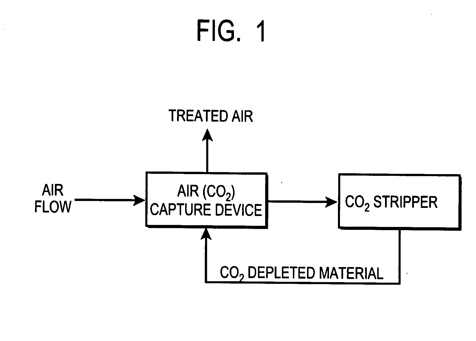
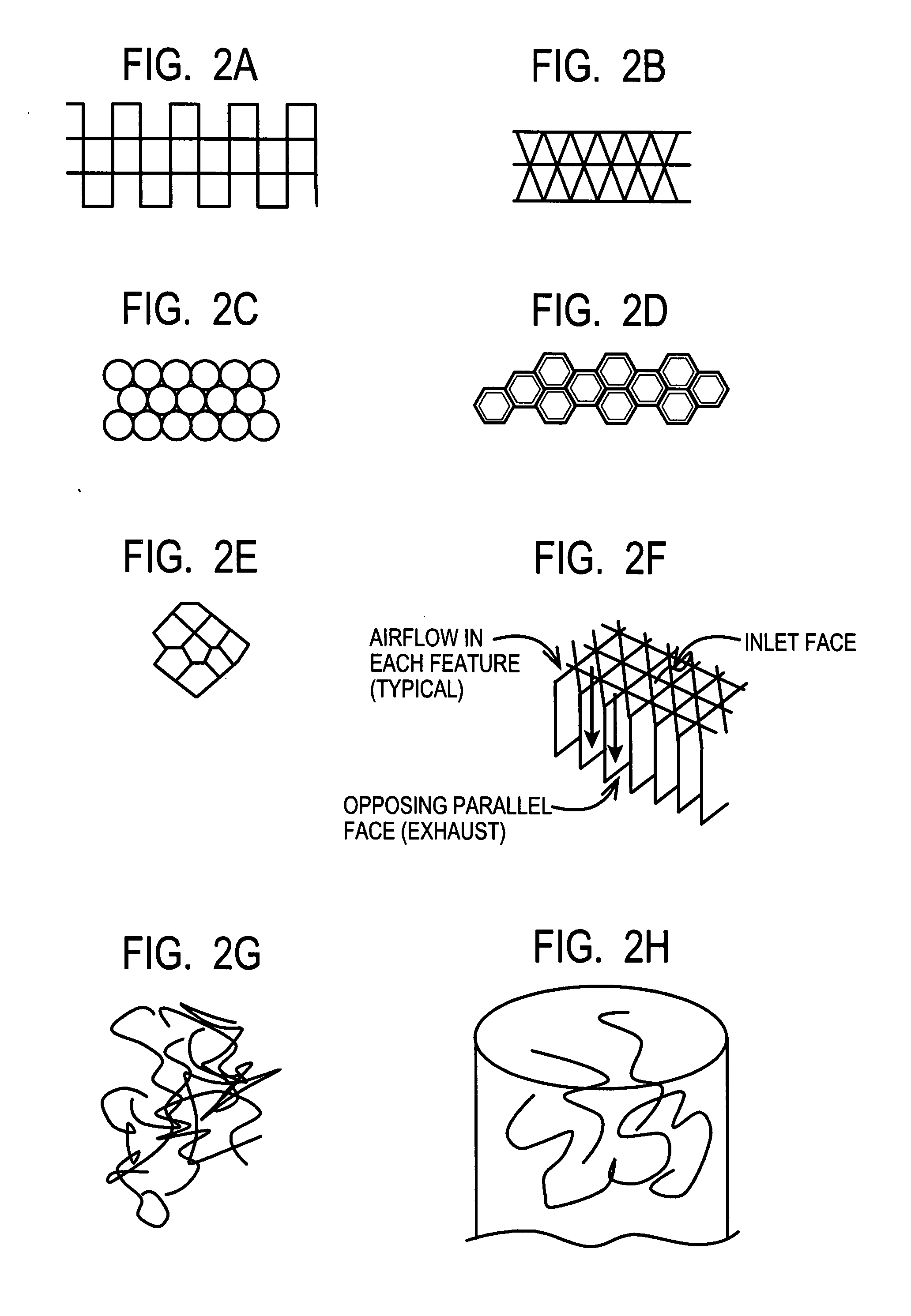
[0021] One goal of the air capture device of the present invention is to present a maximum amount of surface area of the solid phase ion exchange material per unit volume to a high volume flow rate, low pressure air stream while minimizing air pressure drop across the device.

[0022] Preferably, the air capture device also is configured to ensure as complete as possible penetration and thorough liquid contact of all surfaces with a sorbent chemical to remove the captured CO2 and to reactivate the membrane surfaces.

[0023] In operation, the air capture device will be exposed to a stream of air for a given period of time until, through known performance characterization, it will be necessary to remove the captured carbon-bearing molecules and reactivate the solid phase anion exchange materials. The solid phase anion exchange materials will then be treated, for example with a sorbent chemical, e.g. through liquid bath immersion or spray, to remove the carbon-bearing molecules and reacti...


PUM

PropertyMeasurementUnit
thickaaaaaaaaaa
temperatureaaaaaaaaaa
melting pointaaaaaaaaaa

Abstract

An apparatus for capture of CO2 from the atmosphere comprising an anion exchange material formed in a matrix exposed to a flow of the air.

Description

CROSS REFERENCE TO RELATED APPLICATIONS [0001] The present application claims priority from U.S. Provisional Application Ser. No. 60 / 780,466 and 60 / 780,467, both filed Mar. 8, 2006, the contents of which are incorporated herein by reference.BACKGROUND OF THE INVENTION [0002] The present invention in one aspect relates to removal of selected gases from air. The invention has particular utility for the extraction of carbon dioxide (CO2) from air and will be described in connection with such utilities, although other utilities are contemplated, including the sequestration of other gases including NOx and SO2. [0003] There is compelling evidence to suggest that there is a strong correlation between the sharply increasing levels of atmospheric CO2 with a commensurate increase in global surface temperatures. This effect is commonly known as Global Warming. Of the various sources of the CO2 emissions, there are a vast number of small, widely distributed emitters that are impractical to mit...

Claims


Application Information

Patent Timeline
Patent Type & Authority Applications(United States)
IPC IPC(8): B01D53/04C01B31/20C01B32/50F24F11/76
CPCB01D53/0407B01D53/1493Y02C20/20B01D53/22B01D53/62B01D2253/10B01D2253/202B01D2253/206B01D2253/302B01D2253/306B01D2253/3425B01D2257/504B01D2258/06B01D2259/4508C07C1/12Y02C10/04Y02C10/06Y02C10/08Y02C10/10C07C9/04C25B15/08C25B1/34B01J41/04B01J47/00Y02C20/40Y02P20/151B01D59/12B01D2253/25B01D2253/34B01D2259/40083
Inventor WRIGHT, ALLEN B.PETERS, EDDY J.
Owner CARBON SINK
Why Eureka
Try Eureka