Control device for a hybrid electric vehicle

a technology of electric vehicle and control device, which is applied in the direction of electric propulsion mounting, electric devices, transportation and packaging, etc., can solve the problems of vehicle not being properly started and accelerated, and the driving force of the electric motor which is outputted from the motor output system cannot be used

Inactive Publication Date: 2007-09-20
MITSUBISHI FUSO TRUCK AND BUS CORPORATION
View PDF4 Cites 33 Cited by
  • Summary
  • Abstract
  • Description
  • Claims
  • Application Information

AI Technical Summary

Benefits of technology

[0012]An aspect of the present invention is directed to a control device for a hybrid electric vehicle equipped with an engine output system that makes an engine generate a driving force and outputs the driving force of the engine and a motor output system that makes an electric motor generate a driving force and outputs the driving force of the electric motor, the vehicle being capable of transmitting the driving forces outputted from the respective systems to driving wheels, the control device comprising: an automatic transmission that has a plurality of forward gears and transmits to the driving wheels the driving force of the engine which is outputted from the engine output system; a failure detection means for detecting a failure of the motor output system; and a control means that sets a gear of the automatic transmission for start-up of the vehicle to a first gear when the failure is not detected by the failure detection means, and on the other hand, sets the gear of the automatic transmission for start-up of the vehicle to a second gear that is lower than the first gear when the failure is detected by the failure detection means.

Problems solved by technology

In this case, however, the driving force of the electric motor which is outputted from the motor output system cannot be used.
This raises the problem that the vehicle cannot be properly started and accelerated due to the insufficiency of the driving force transmitted to the driving wheels.

Method used


Image

  • Control device for a hybrid electric vehicle
  • Control device for a hybrid electric vehicle
  • Control device for a hybrid electric vehicle

Examples


Embodiment Construction

[0022]An embodiment of the present invention will now be described with reference to the attached drawings.

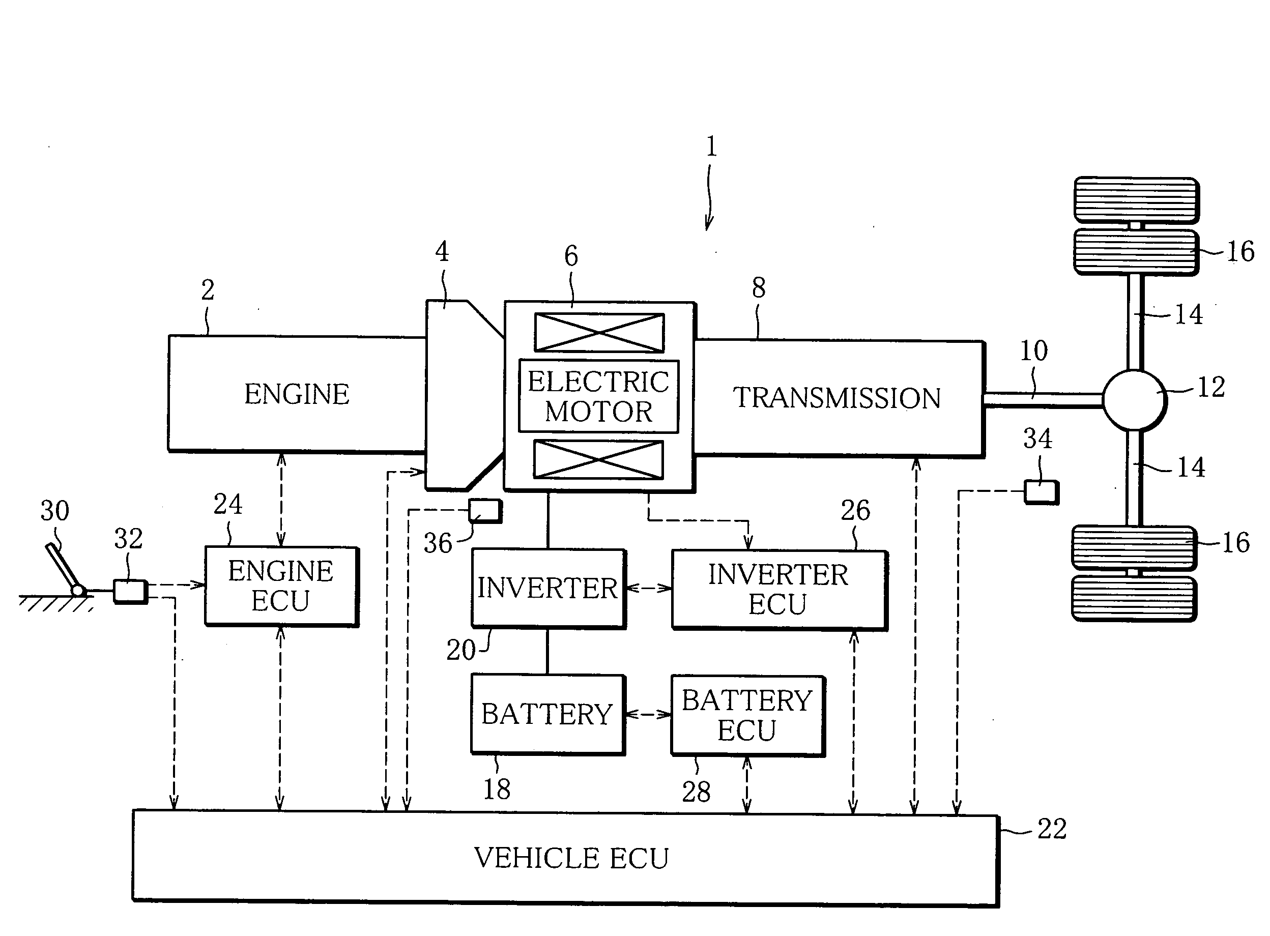
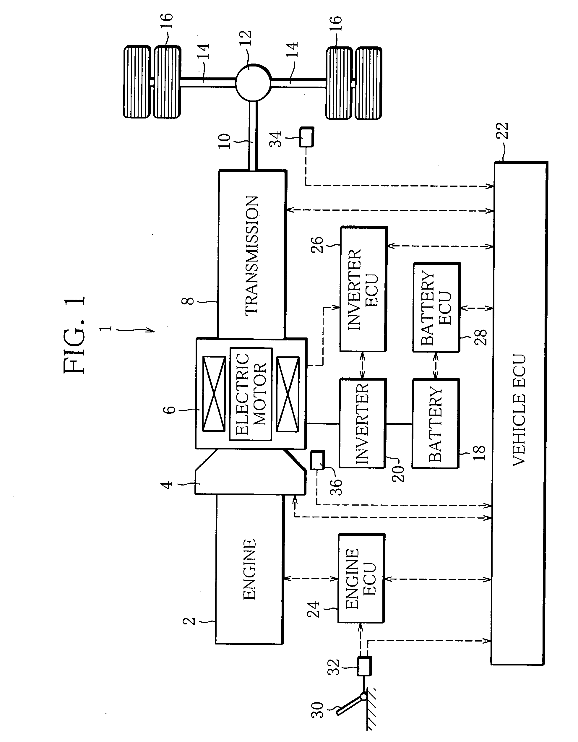
[0023]FIG. 1 is a diagram showing a substantial part of a hybrid electric vehicle 1 to which the present invention is applied.

[0024]An input shaft of a clutch 4 is coupled to an output shaft of an engine 2, which is a diesel engine. An output shaft of the clutch 4 is coupled to an input shaft of an automatic transmission (hereinafter referred to as transmission) 8 having five forward gears (hereinafter referred to simply as gears) through a rotary shaft of a permanent-magnetic synchronous motor (hereinafter referred to as electric motor) 6. An output shaft of the transmission 8 is connected to left and right driving wheels 16 through a propeller shaft 10, a differential gear unit 12 and driving shafts 14.

[0025]Therefore, when the clutch 4 is engaged, both the output shaft of the engine 2 and the rotary shaft of the electric motor 6 can be mechanically connected with the driving...


PUM


Abstract

A hybrid electric vehicle is equipped with an engine output system that makes the engine generate a driving force and outputs the driving force of the engine and a motor output system that makes an electric motor generate a driving force and outputs the driving force of the electric motor, and is capable of transmitting to driving wheels the driving forces outputted from the respective systems. If a failure of the motor output system is not detected, a vehicle ECU sets the gear of an automatic transmission for start-up of the vehicle to a first gear. If the failure is detected, the vehicle ECU sets the gear of the automatic transmission for start-up the vehicle to a second gear that is lower than the first gear.

Description

BACKGROUND OF THE INVENTION[0001]1. Field of the Invention[0002]The present invention relates to a control device for a hybrid electric vehicle, and more specifically to a control device for a hybrid electric vehicle capable of transmitting a driving force of an engine and that of an electric motor to driving wheels of a vehicle.[0003]2. Description of the Related Art[0004]A hybrid electric vehicle equipped with an engine output system that makes an engine generate a driving force and outputs the driving force and a motor output system that makes an electric motor generate a driving force and outputs the driving force has conventionally been well known. As a hybrid electric vehicle of this type, a parallel hybrid electric vehicle capable of transmitting the driving forces outputted from both the systems to the driving wheels of the vehicle has been developed and in practical use.[0005]Such a parallel hybrid electric vehicle is proposed, for example, in Unexamined Japanese Patent Pub...

Claims


Application Information

Patent Timeline
Patent Type & Authority Applications(United States)
IPC IPC(8): B60K1/02B60K6/48B60K6/547B60L50/16B60W10/02B60W10/06B60W10/08B60W10/10B60W10/18B60W20/00F16H59/74F16H61/10F16H61/12F16H61/68
CPCB60K6/48B60K6/547B60W10/06B60W10/08Y10T477/23B60W20/00Y02T10/6221Y02T10/6286B60W10/115B60L3/0061B60L15/2072B60L2240/12B60L2240/421B60L2240/423B60L2240/486B60L2240/507B60L2240/526B60L2240/529B60L2240/545B60L2240/547B60L2240/549B60L2250/26B60L2240/527Y02T10/72B60L50/16Y02T10/62Y02T10/64Y02T10/7072B60W30/18027B60W10/11B60W10/26B60W20/50Y02T10/70
Inventor OGATA, MAKOTOKIUCHI, TATSUO
Owner MITSUBISHI FUSO TRUCK AND BUS CORPORATION
Why Eureka
Try Eureka