Integrated circuit device, diagnosis method and diagnosis circuit for the same

a technology of integrated circuits and diagnostic circuits, applied in measurement devices, instruments, computing, etc., can solve problems such as the inability to perform hardware diagnosis methods, and achieve the effect of reducing the cost of assembling the apparatus and improving the reliability of the disk array apparatus

Inactive Publication Date: 2007-09-20
HITACHI LTD
View PDF4 Cites 23 Cited by
  • Summary
  • Abstract
  • Description
  • Claims
  • Application Information

AI Technical Summary

Benefits of technology

[0015] According to the invention, it is possible to prevent the occurrence of abnormalities such as breakdowns or failures in an apparatus such as a disk array apparatus after mounting the logical circuit (diagnosis target) in a disk array apparatus, and it is thereby possible...

Problems solved by technology

However, as a method for performing hardware diagnosis before shipment, there is only one method—performing hardware diagnosis of each package individually by using a ...

Method used


Image

  • Integrated circuit device, diagnosis method and diagnosis circuit for the same
  • Integrated circuit device, diagnosis method and diagnosis circuit for the same
  • Integrated circuit device, diagnosis method and diagnosis circuit for the same

Examples


Embodiment Construction

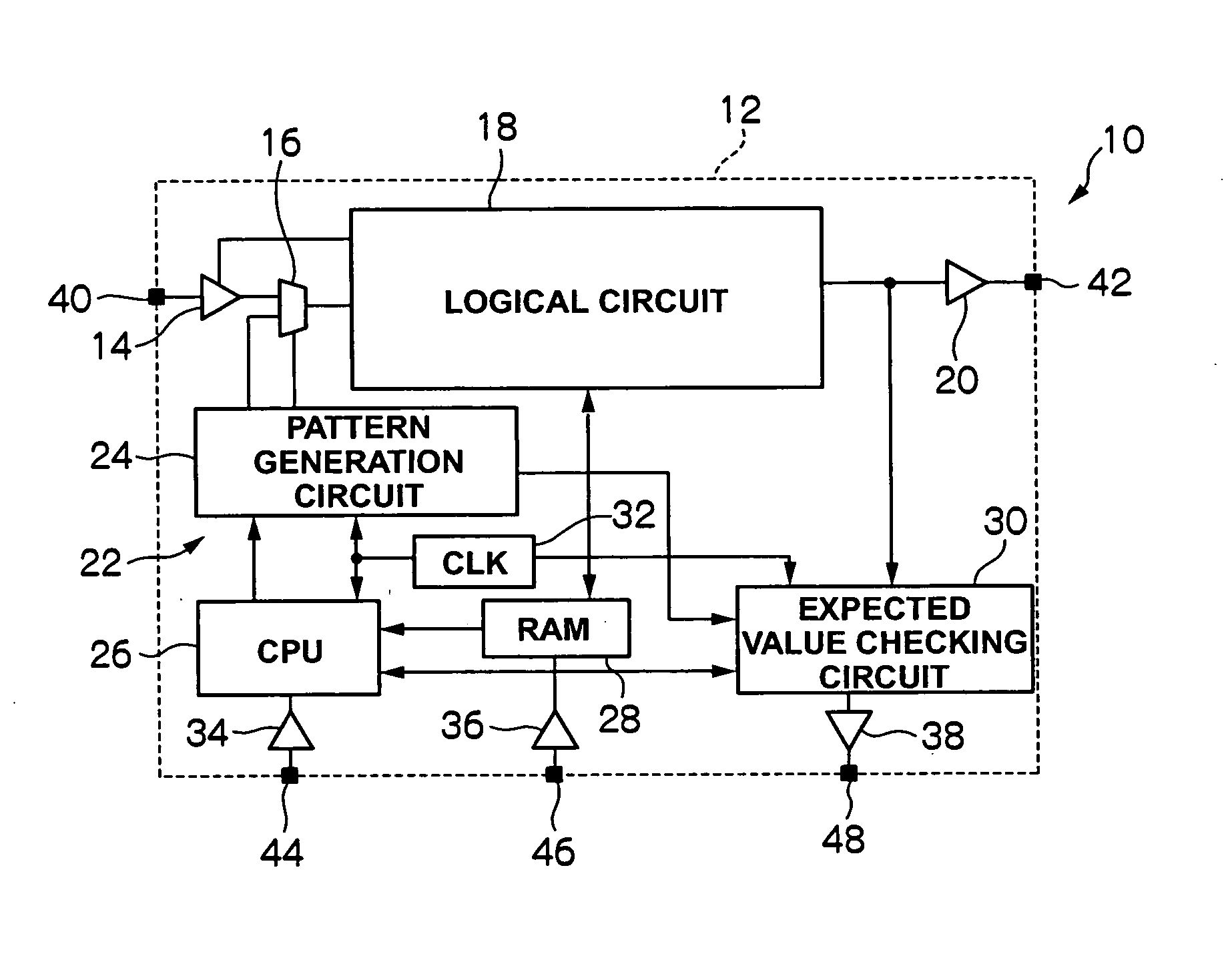
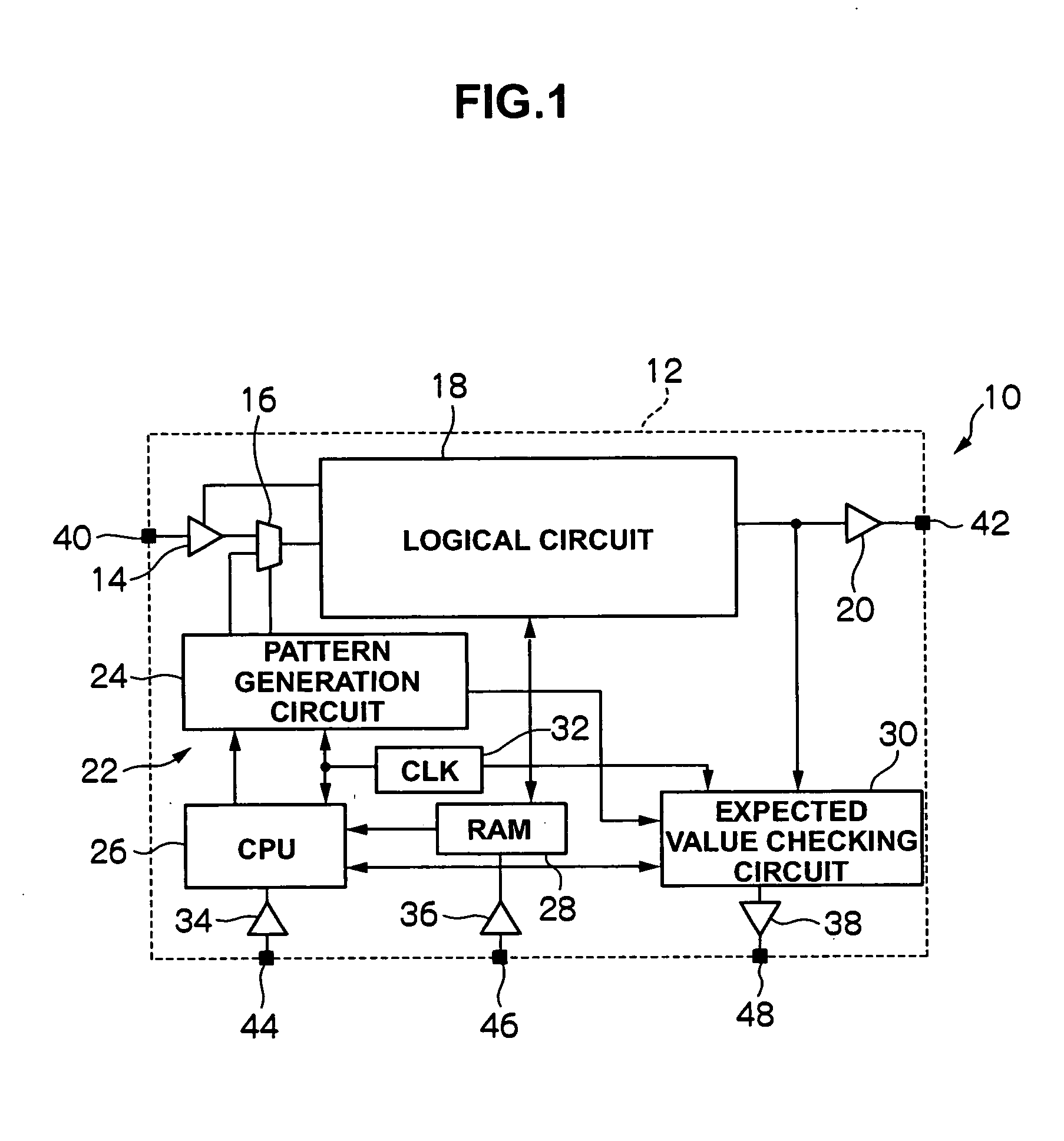
[0038] Embodiments of this invention will be described below with reference to the attached drawings. FIG. 1 is a block diagram of a large scale integrated circuit device with a self-diagnosis circuit for a disk array apparatus. FIG. 1 shows that the large scale integrated circuit device with a self-diagnosis circuit for a disk array apparatus (hereinafter referred to as the “disk array apparatus LSI”) 10 includes an LSI board 12. A buffer (input buffer) 14, a selector (input selector) 16, a logical circuit 18, a buffer (output buffer) 20, and a self-diagnosis circuit (test control circuit) 22 are located on the board 12. The self-diagnosis circuit 22 includes a pattern generation circuit 24, a CPU (Central Processing Unit) 26, RAM (Random Access Memory) 28, an expected value checking circuit 30, a clock signal generation circuit 32, buffers (input buffers) 34 and 36, and a buffer (output buffer) 38. Clock signal(s) generated by the clock signal generation circuit 32 are supplied to...


PUM


Abstract

Hardware diagnosis of a disk array apparatus is conducted before shipment by using a self-diagnosis circuit, using the same criteria that apply to actual [in-use] equipment.
A logical circuit 18 and a self-diagnosis circuit 22 are mounted on an LSI 10. When a test program is loaded to a RAM 28 and a diagnosis command is input to a CPU 26 before shipment, a pattern generation circuit 24 generates a pattern and expected value pattern data corresponding to the pattern under the control of the CPU 26. When the pattern is input to the logical circuit 18, the logical circuit 18 operates according to the pattern and outputs pattern data showing the test result. An expected value checking circuit 30 compares and checks this pattern data against the expected value pattern data and then outputs the diagnosis result regarding whether the logical circuit 18 is normal or abnormal. The content of the diagnosis result is displayed on an external display unit.

Description

CROSS-REFERENCES TO RELATED APPLICATIONS [0001] This application relates to and claims priority from Japanese Patent Application No. 2006-49830, filed on Feb. 27, 2006, the entire disclosure of which is incorporated herein by reference. BACKGROUND OF THE INVENTION [0002] The present invention relates to an integrated circuit device, and particularly to one with a self-diagnosis circuit mounted thereon. In particular, this invention relates to a large scale integrated circuit device having a hardware diagnosis function for a disk array apparatus. The invention further relates to a method for diagnosing a large scale integrated circuit device for a disk array apparatus, and in particular, an effective method for applying the diagnosis of a disk array apparatus to an integrated circuit device before shipment of the integrated circuit device. [0003] Hardware diagnosis of a disk array apparatus conventionally has been conducted by either of the following methods: individually performing ...

Claims


Application Information

Patent Timeline
IPC IPC(8): G01R31/28
CPCG01R31/31921G01R31/31919
Inventor SATO, TSUTOMU
Owner HITACHI LTD
Why Eureka
Try Eureka