High-temperature pipeline

a pipeline and high-temperature technology, applied in the direction of collector thermal insulation, machines/engines, light and heating apparatus, etc., can solve the problems of destroying land, fossil fuel resource dwindling, and the true cost of fossil fuel based electrical generation is only now being understood

Inactive Publication Date: 2007-09-27
BRIGHTSOURCE ENERGY
View PDF40 Cites 76 Cited by
  • Summary
  • Abstract
  • Description
  • Claims
  • Application Information

AI Technical Summary

Problems solved by technology

However, the side affects of nearly one hundred years of fossil fuel use for generating power has resulted in a diminishment of fossil fuel resources at the same time as world demand for energy and power is increasing, geopolitical instability as a result of real or perceived bias in favor of oil producing countries, and environmental impact ranging from ruination of land and other natural resources as coal is strip mined, to greenhouse gas emission based global warming.
As a result, the true cost of fossil fuel based electrical generation is only now just being understood, and the immediate cost, based on the trade value of fossil fuel, is rapidly increasing as supply is outstripped by demand.
A common difficulty associated with the generation of steam for electrical generation using solar insulation is the inability to concentrate heat to generate steam in sufficient quantity at specific quality to effectively and economically generate electricity which can compete in price and reliability with fossil fuel based electrical generation.

Method used


Image

  • High-temperature pipeline
  • High-temperature pipeline
  • High-temperature pipeline

Examples


Embodiment Construction

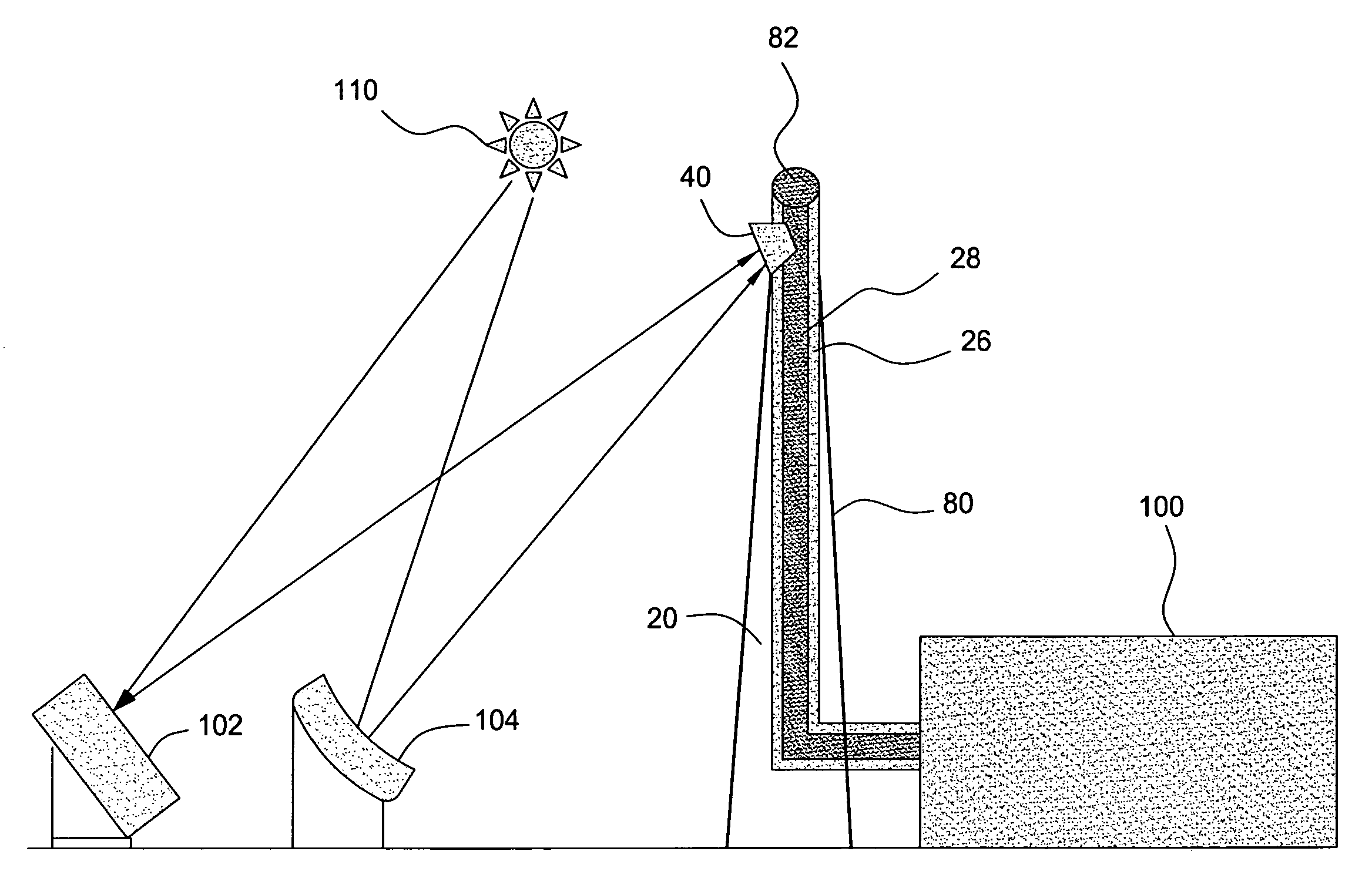
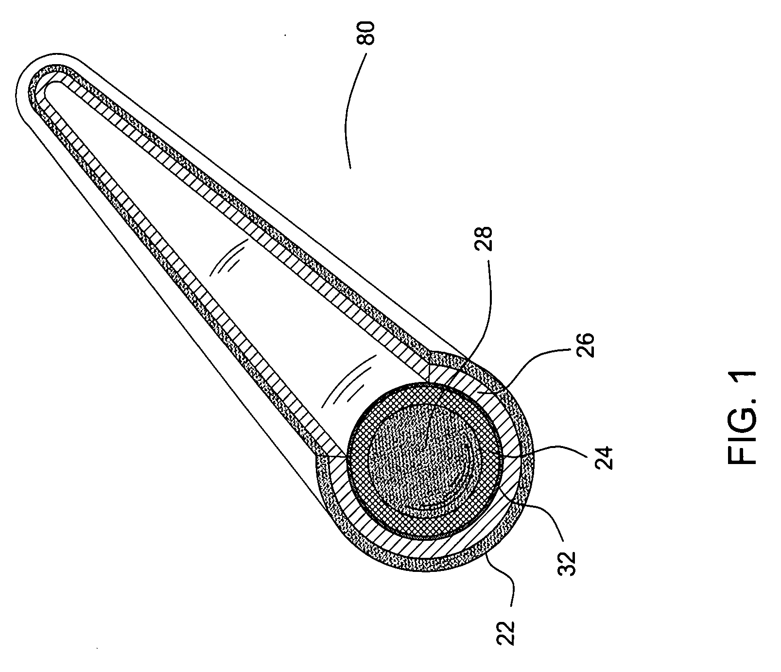
[0024] Reference is now made to FIG. 1 in which a dual walled conveyance forming a high-temperature energy transportation pipeline 20 is shown which comprises an outer tubing 22 and an inner tubing 24, having a gap therebetween forming a flow annulus 26. Within inner tubing 24 is provided a flow conduit 28. Both the outer tubing 22 and the inner tubing 24 may be constructed from materials such as carbon steel and others well known to one skilled in the art. Pipeline 20 enables the delivery of a fluid, or gas to a location, and passage of that fluid back to its origin through the pipeline 20. To accomplish this, and to minimize temperature change of the returning fluid, the flow annulus 26 is used to transport cooler fluids and the flow conduit 28 is used to transport hotter fluids. Such fluids include water / steam, air, helium, argon, and molten salts. To help increase the likelihood of a constant temperature differential between the flow volume 28 and the flow annulus 26 a high effi...


PUM


Abstract

A solar insulation capturing and transporting system includes a solar insulation receiving member configured in combination with a dual walled conduit. Fluid is flowed through one portion of the conduit and into the solar insulation receiving member and thence into a second portion of the conduit. Heat energy captured in the fluid is then transferred, in the flowing fluid, to a use location where the energy may be usefully exploited.

Description

CROSS-REFERENCE TO RELATED APPLICATIONS [0001] This application claims benefit of U.S. provisional patent application Ser. No. 60 / 779,983, filed Mar. 7, 2006, which is herein incorporated by reference.BACKGROUND OF THE INVENTION [0002] 1. Field of the Invention [0003] The present invention relates to the field of the generation of energy. More particularly, the invention relates to the generation of energy using heat, including energy generated using solar insulation directly or indirectly as a heat source. [0004] 2. Description of the Related Art [0005] The generation of energy for purposes of power generation, including the direct conversion of energy to power such as through the use of an internal combustion engine to drive a shaft to rotate a tire for powering a vehicle, as well as the indirect use of using that rotating shaft to drive a generator for the generation of electricity has relied predominately on fossil fuel energy sources for nearly 100 years. Fuels such as oil, nat...

Claims


Application Information

Patent Timeline
Patent Type & Authority Applications(United States)
IPC IPC(8): F24J2/24F24S10/70
CPCF03G6/005F05B2220/301F24J2/0483F24J2/07Y02E10/46F28F1/003Y02E10/41Y02E10/44F24J2/51F24S80/60F24S20/20F24S10/25Y02E10/40
Inventor GOLDMAN, ARNOLD J.
Owner BRIGHTSOURCE ENERGY
Why Eureka
Try Eureka