Solar power plant

a solar power plant and solar energy technology, applied in the direction of machines/engines, separation processes, lighting and heating apparatus, etc., can solve the problems of their efficiency, cost and complexity, and achieve the effect of low construction cost, high reliability in operation and simple structur

Active Publication Date: 2007-09-27
DIVERSIFIED SOLAR SYST LLC
View PDF35 Cites 18 Cited by
  • Summary
  • Abstract
  • Description
  • Claims
  • Application Information

AI Technical Summary

Benefits of technology

[0008] The resulting solar energy collector is simple in construction low in cost, and highly reliable in operation.

Problems solved by technology

These devices all differ in their efficiency and in their cost and complexity.

Method used


Image

  • Solar power plant
  • Solar power plant
  • Solar power plant

Examples


Embodiment Construction

[0015] As required, detailed embodiments of the present invention are disclosed herein; however, it is to be understood that the disclosed embodiments are merely exemplary of the invention that may be embodied in various and alternative forms. The Figures are not necessarily to scale; some features may be exaggerated or minimized to show details of particular components. Therefore, specific structural and functional details disclosed herein are not to be interpreted as limiting, but merely as a representative basis for the claims and / or as a representative basis for teaching one skilled in the art to variously employ the present invention.

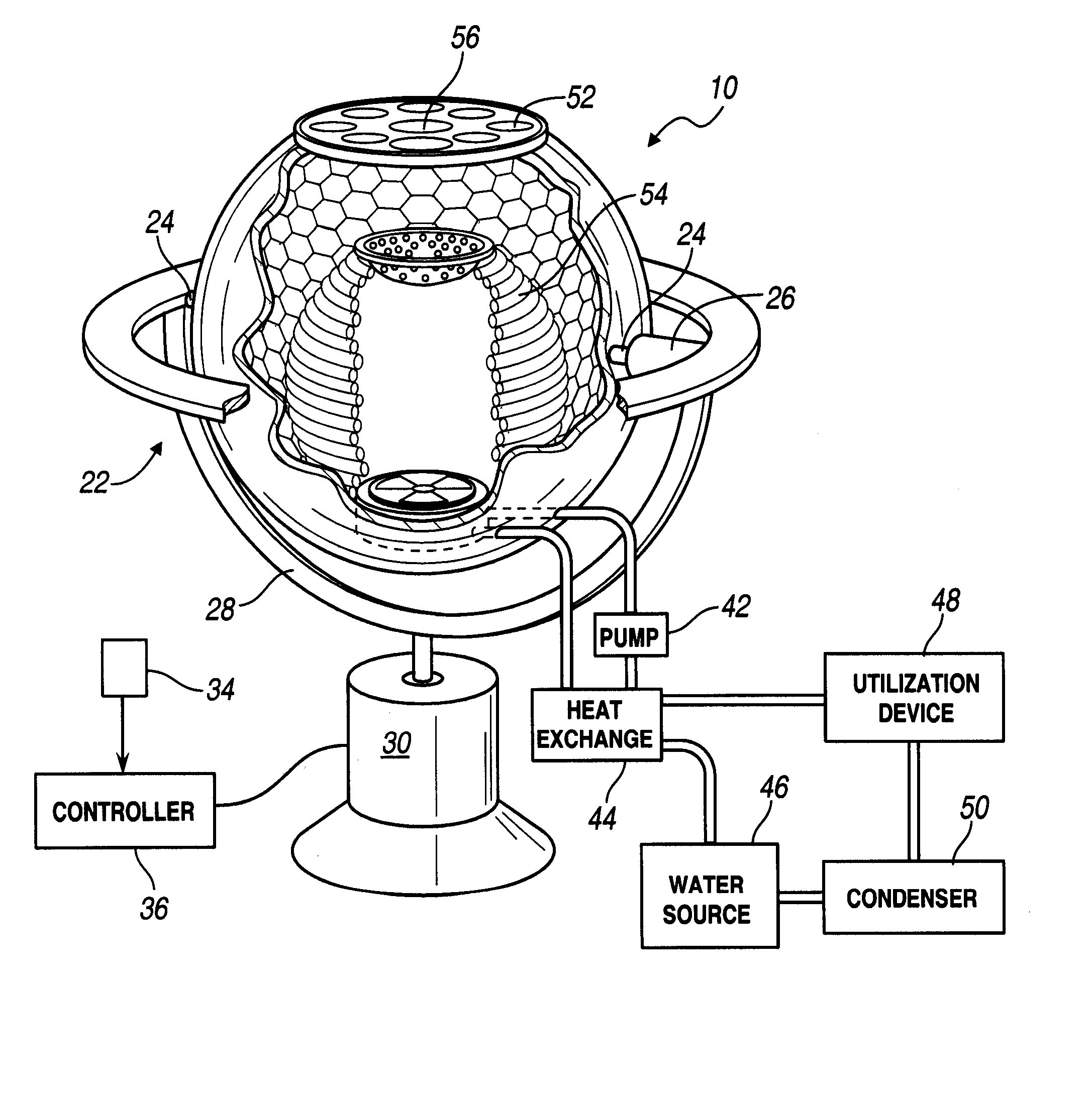
[0016] The solar collector of the present invention is constructed about a rigid container, generally indicated at 10 in FIG. 1. The container 10 is shown as being a sphere in the depicted embodiment, but other shapes are useful in connection with the present invention such as rectangular, oval, etc. The wall 12 of the container 10 is rigid and ma...


PUM


Abstract

A collector for solar energy is disclosed having a closed hollow partially spherical container with a window for permitting solar energy to enter the container. The container has a reflective inner surface for retaining the energy. The collecting lens focuses the solar energy. Central tubing is provided and a pump circulates fluid through the tubing to a heat exchanger for transferring thermal energy from the fluid in the tubing to a utilization device.

Description

CROSS-REFERENCE TO RELATED APPLICATIONS [0001] This application claims the benefit of U.S. Provisional Application Ser. No. 60 / 783,956, filed Mar. 20, 2006.FIELD OF THE INVENTION [0002] This invention relates to an apparatus for capturing solar energy and using that energy for various power purposes such as boiling water, building heating, desalinization and the like. BACKGROUND OF THE INVENTION [0003] A variety of solar energy collectors have been proposed, particularly for use in areas in the middle latitudes which have a high percentage of sunlight. The energy produced may be used to desalinate water, produce thermal power for cooking or industrial operations, and a wide variety of similar uses. These devices all differ in their efficiency and in their cost and complexity. The present invention is accordingly directed toward a unit which is relatively simple in construction so as to be low in cost and reliable in operation and which converts a high percentage of the incident sola...

Claims


Application Information

Patent Timeline
Patent Type & Authority Applications(United States)
IPC IPC(8): F24J2/08F24J2/00F24S23/30
CPCB01D1/0035F03G6/005F05B2220/301F24J2/06F24J2/07Y02E10/46F24J2/085F24J2/13Y02B10/20Y02E10/41Y02E10/44F24J2/08F24S20/20F24S23/00F24S23/30F24S23/31F24S23/72Y02P70/10Y02A20/212Y02E10/40
Inventor POLK, STEVEN
Owner DIVERSIFIED SOLAR SYST LLC
Why Eureka
Try Eureka