

Fixture and method of holding and debonding a workpiece with the fixture
- Summary
- Abstract
- Description
- Claims
- Application Information
AI Technical Summary
Benefits of technology
Problems solved by technology
Method used
Image

Examples
first embodiment
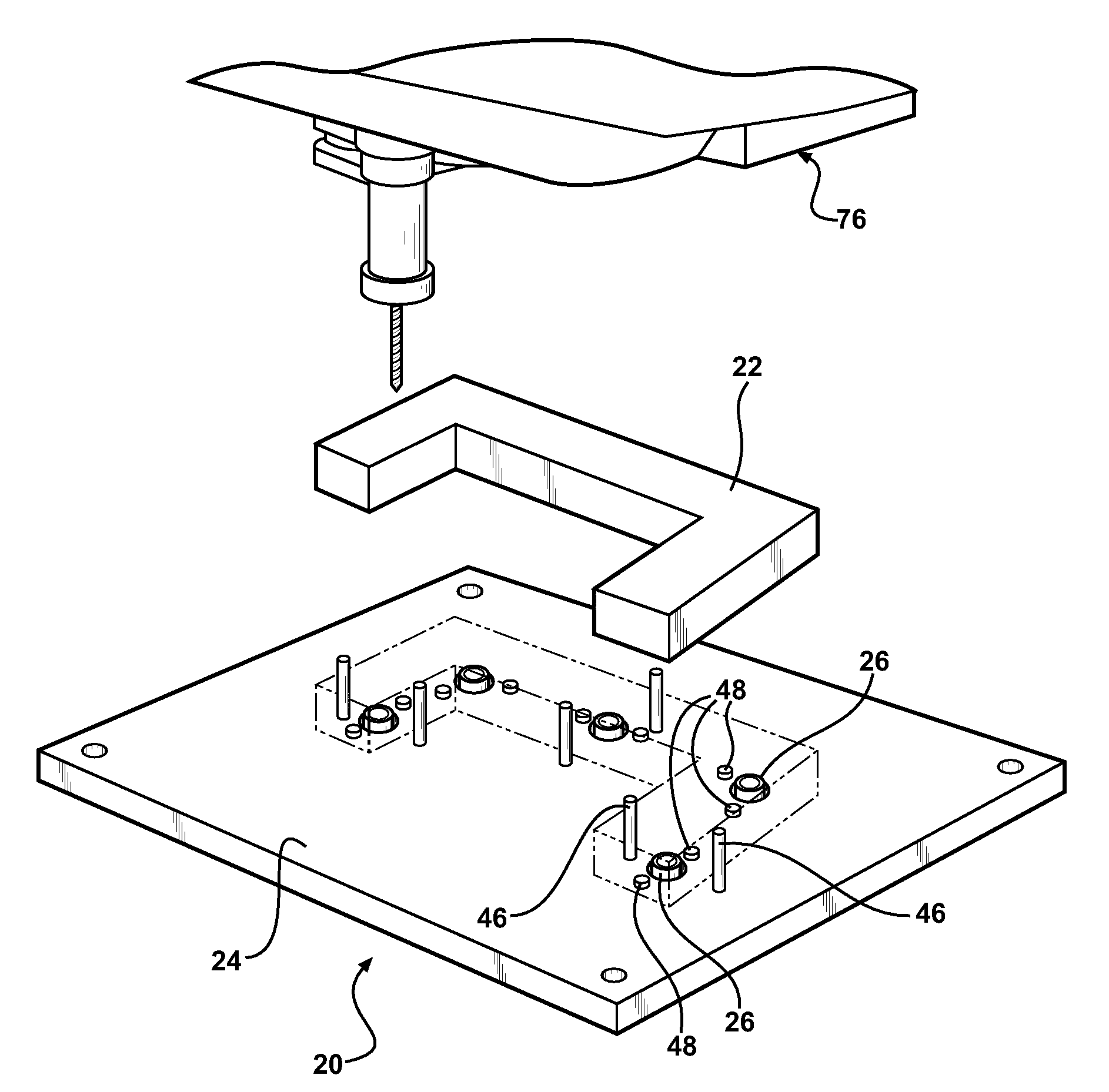
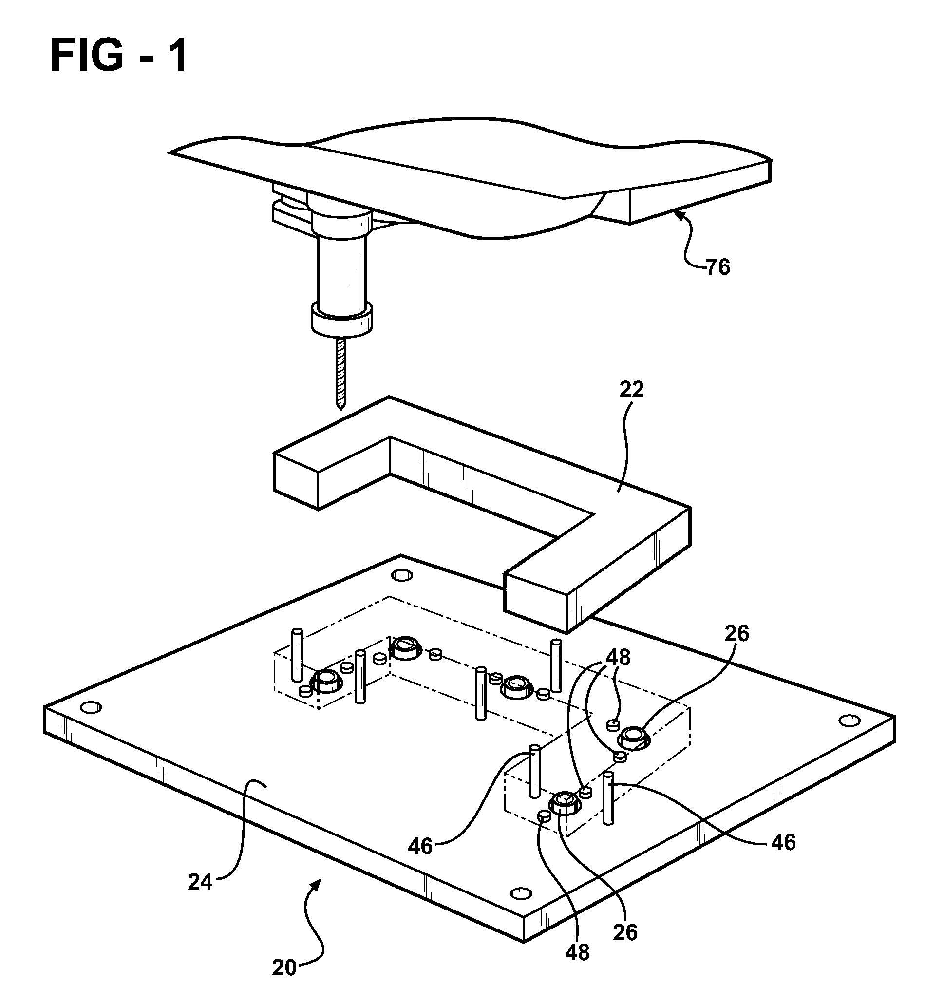
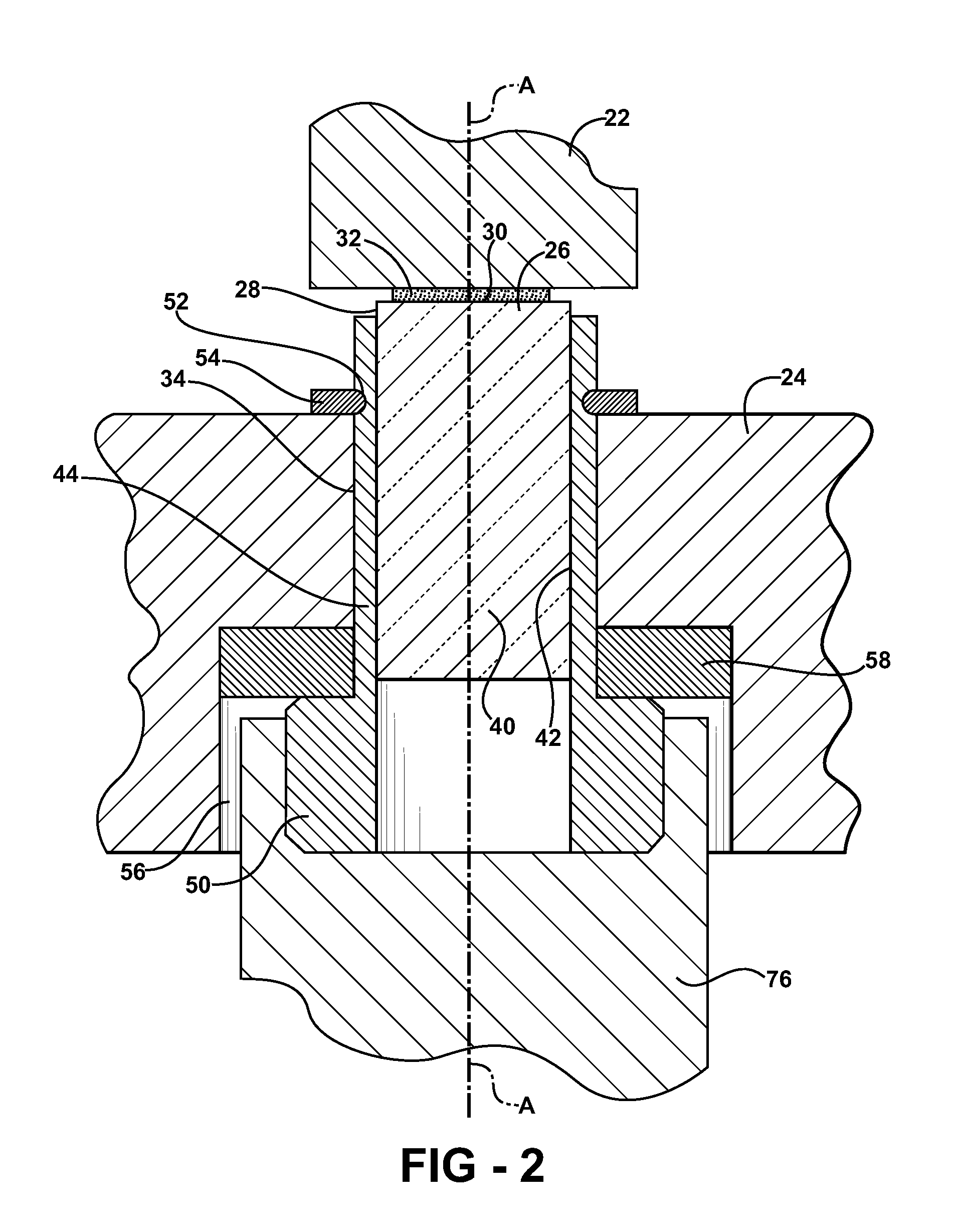
[0034]In the fixture 20, the rod 26 is rotatable about the axis A relative to the base 24. Rotation of the rod 26 relative to the base 24 is an adhesive bond destroying motion. Specifically, as shown in FIG. 2, the rod 26 is rotatable about the axis A in the bore 34. For example, the motor 76 such as a pneumatic motor, a hydraulic motor, or an electric motor is coupled to the rod 26 to rotate the rod 26 about the axis A relative to the base 24. Alternatively, a hand tool, such as a screw driver, is used to rotate the rod 26 about the axis A.
[0035]As shown in FIG. 2, the rod 26 includes a head 50 opposite the bonding surface 30 on the rod 26. The rod 26 defines a groove 52 spaced opposite from the head 50 relative to the base 24 and a snap ring 54 is engaged the groove 52. The head 50 and the snap ring 54 are sized larger than the bore 34 for rotatably maintaining the rod 26 in the bore34.
[0036]Specifically, the base 24 defines a counterbore 56 being concentric with the bore 34. The ...
second embodiment
[0037]In the fixture 20, the rod 26 is linearly translatable relative to the base 24 along the axis A. Specifically, as shown in FIG. 3, the rod 26 is linearly moveable along the axis A in the bore 34. For example, the motor 76 such as a pneumatic motor, a hydraulic motor, or an electric motor is coupled to the rod 26 to linearly translate the rod 26 along the axis A relative to the base 24. Alternatively, a hand tool is used to linearly translate the rod 26 along the axis A. More specifically, a linear force may be applied to the head 50 of the rod 26 to linearly translate the rod 26 relative to the base 24 along the axis A.
[0038]Preferably, the base 24 includes a linear bearing 60 immovably engaged in the bore 34 and slideably engaged with the rod 26. The linear bearing 60 enables the rod 26 to freely move relative to the base 24 in the bore 34.
[0039]For example, and as shown if FIG. 3, the fixture 20 includes a lever 62 coupled to the rod 26. Specifically, the lever 62 is dispose...
third embodiment
[0040]In the fixture 20, the rod 26 is both rotatable about the axis A relative to the base 24 and linearly translatable along the axis A relative to the base 24. For example, as shown in FIG. 4, the base 24 defines the bore 34 and threads 66 in the bore 34. The rod 26 is threaded and threadedly engages the bore 34. The threads 66 in the bore 34 correspond to the threaded rod 26 such that the rod 26 is rotatable relative to the threads 66.
[0041]Preferably, the threads 66 are shallow. Shallow threads 66 increase the mechanical advantage of the rod 26 as compared to deep threads 66 by increasing the rotational stress on the adhesive 32 relative to the normal stress on the adhesive 32.
[0042]For example, the motor 76 such as a pneumatic motor, a hydraulic motor, or an electric motor is coupled to the rod 26 to rotate the rod 26 relative to the threads 66. Alternatively, a hand tool, such as a screw driver, is used to rotate the rod 26 relative to the threads 66. More specifically, rotat...
PUM
| Property | Measurement | Unit |
|---|---|---|
| Force | aaaaa | aaaaa |
| Adhesivity | aaaaa | aaaaa |
| Energy | aaaaa | aaaaa |
Abstract
Description
Claims
Application Information