Device for Clamping in Centered Position Parts to be Subjected to Machining and Machine

a technology of machining and clamping parts, applied in the direction of tyres, metal-working holders, supporters, etc., can solve the problems of manual setup, time-consuming and costly, and the maximum travel of the centering element cannot allow the full dimensional range to be encompassed

Inactive Publication Date: 2007-09-27
MAUS SPA
View PDF18 Cites 18 Cited by
  • Summary
  • Abstract
  • Description
  • Claims
  • Application Information

AI Technical Summary

Benefits of technology

[0008] The problem underlying the present invention is to provide a device for clamping in centered position semi-finished parts to be subjected to machining, which device is structurally and functionally designed to overcome the shortcomings stated with reference to the cited prior art.

Problems solved by technology

When such devices are used in processing lines in which the parts supplied to the machining centers exhibit, in random sequences, different dimensions within relatively wide dimensional ranges (in the case of wheels, the nominal diameter of the semifinished products may vary, for example, between 13 and 24 inches), the maximum extent of travel of the centering elements does not allow the entire dimensional range to be encompassed.
Furthermore, since it is preferable for it to be possible to supply the parts to the machining centers substantially randomly, so resulting in sequences of semi-finished parts which differ in dimensions from one another, the variation in the dimensions of the part to be machined makes setup, which is conventionally almost always performed manually, time-consuming and costly.

Method used


Image

  • Device for Clamping in Centered Position Parts to be Subjected to Machining and Machine
  • Device for Clamping in Centered Position Parts to be Subjected to Machining and Machine
  • Device for Clamping in Centered Position Parts to be Subjected to Machining and Machine

Examples


Embodiment Construction

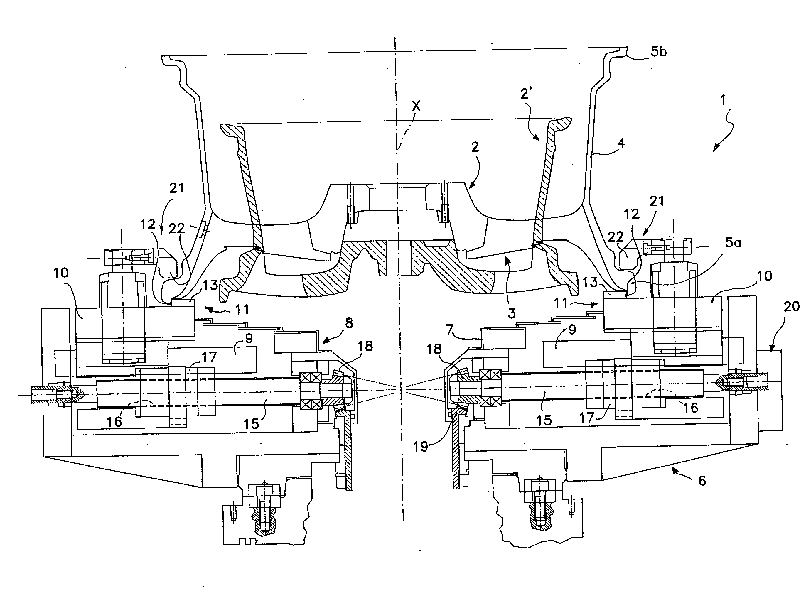
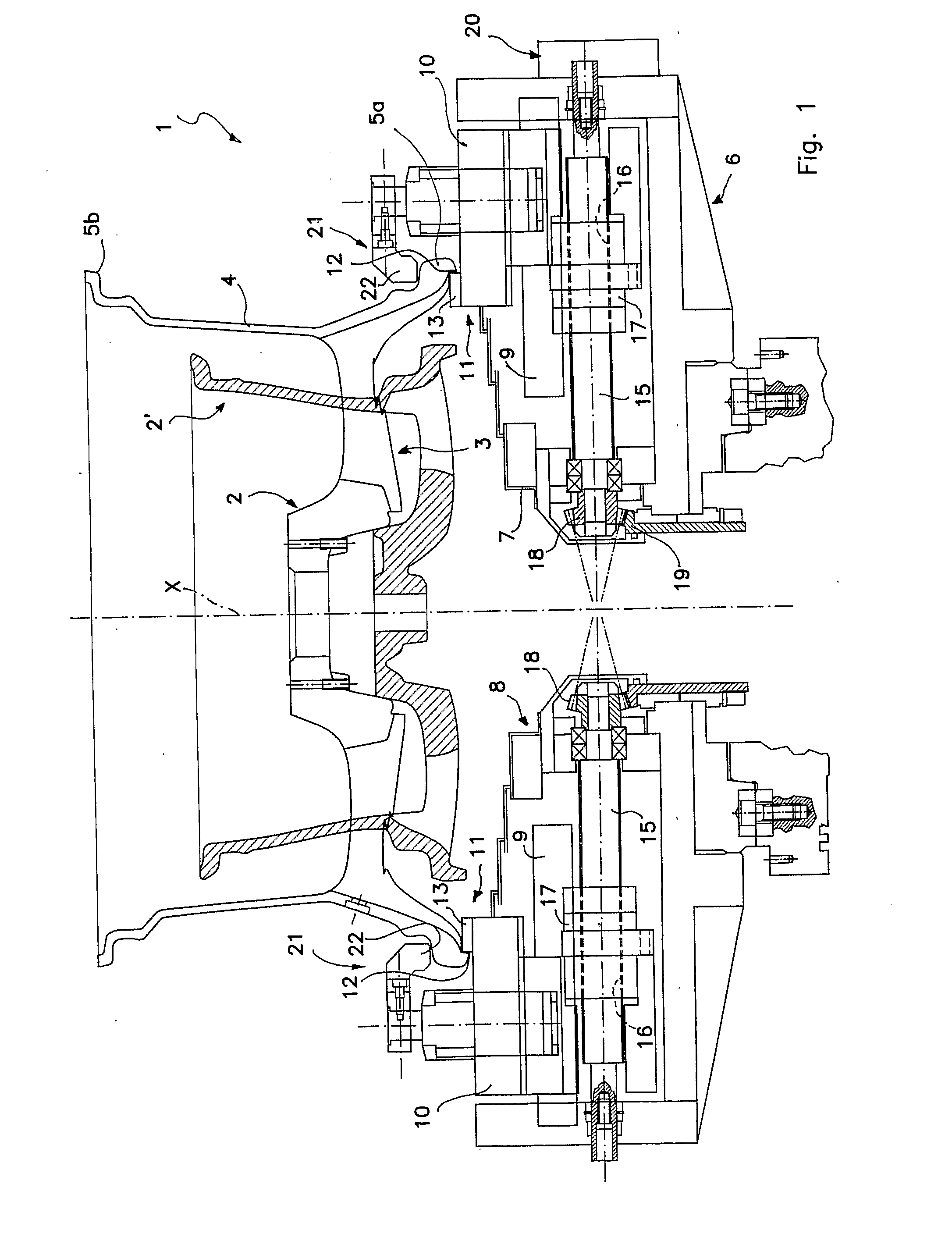
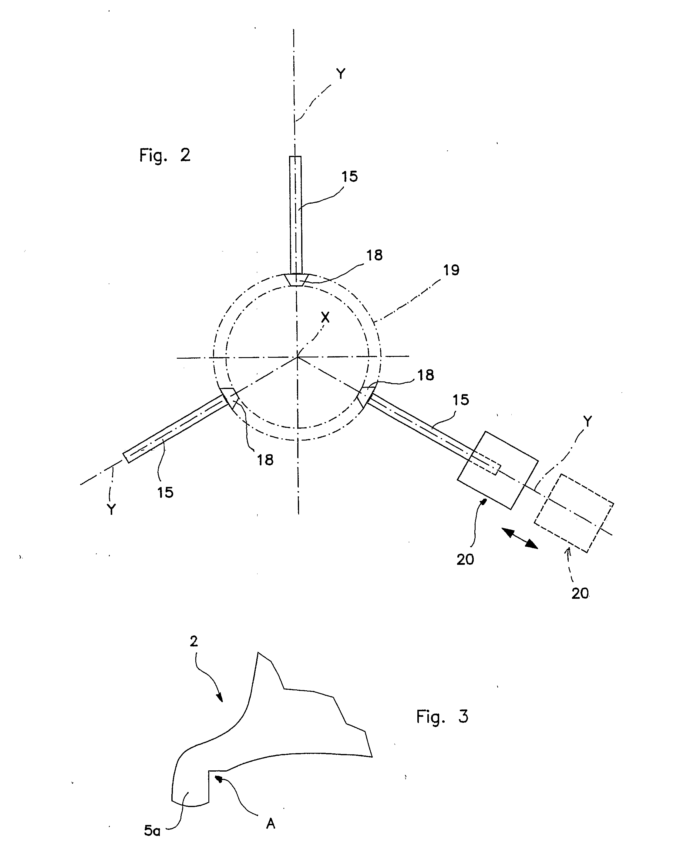
[0017] With initial reference to FIGS. 1 to 3, 1 denotes overall a first example of a device for centering and clamping (semi-finished or less than semi-finished) parts which are intended to be subjected to subsequent machining, said device being in accordance with the present invention. Said device is described below with particular reference to semi-finished vehicle wheels 2 made from light alloy, in particular from aluminium alloy, it nevertheless being understood that said application constitutes a preferred but non-limiting choice as the invention may equally effectively be applied in any case in which there is a requirement to centre and clamp parts of an axially symmetrical geometry (such as for example brake disks, flywheels, drums and others).

[0018] In the present context, the term “wheel” is intended to denote the overall rim and wheel structure for vehicles, typically provided with a perforated front portion 3 (comprising through-holes for attaching the rim to the vehicl...


PUM


Abstract

A device is described for clamping parts in a centered position which are to be machined, including a device for centring the part on a worktable including at least three centering elements with a regular angular spacing. Each centering element is displaceable along a predetermined radial direction (Y), and there are actuating devices associated with each respective centering element for operational actuation thereof in the translational movement along the corresponding radial direction (Y). Each actuating device, for each centring element, includes a an actuating element capable of being driven in a rotational motion and a first motion transmission device capable of converting the rotational motion of the actuating element into translational motion of the corresponding centering element along the corresponding radial direction (Y), and a second motion transmission device between the actuating elements capable of synchronously transmitting the rotational motion of one of the actuating elements to the other actuating elements so as to impart a synchronized translational movement of the centering elements along the respective radial translation directions (Y).

Description

[0001] This application is a U.S. National Phase Application of PCT International Application PCT / IT2004 / 000678 which is incorporated by reference herein.TECHNICAL FIELD [0002] The present invention relates to a device for centering and clamping parts to be subjected to machining including a part centering device and actuating means. The invention also provides a machine tool comprising the device. BACKGROUND OF THE INVENTION [0003] The invention concerns in particular, although not exclusively, the specific technical object of centering parts to be subjected to machining, for example turning or other surface finishing, with the aim of effecting centering of the part relative to the geometric axis of rotation of the equipment or worktables typically provided in conventional machining centers. Although the invention may be used in any machining center where it is necessary to center parts with substantially axially symmetrical geometry, it was devised with particular reference to the...

Claims


Application Information

Patent Timeline
Patent Type & Authority Applications(United States)
IPC IPC(8): B60B30/00B23Q3/18
CPCB23Q3/183B23Q3/062B60B30/00B23Q3/18
Inventor SAMMARTIN, ROBERTOVELENTINI, BRUNO
Owner MAUS SPA
Why Eureka
Try Eureka