Inductive heated injector using a three wire connection

Active Publication Date: 2007-09-27
VITESCO TECH USA LLC
View PDF31 Cites 26 Cited by
  • Summary
  • Abstract
  • Description
  • Claims
  • Application Information

AI Technical Summary

Benefits of technology

[0007]An example fuel injector assembly includes a first coil driven by a DC current driver and a second coil driven by an AC dri

Problems solved by technology

Further, alternate fuels such as ethanol perform poorly in cold conditions, and therefore also benefit from pre-heating of fuel.
Seals required between the wires and pressure barriers are a potential source of fuel leakage and are therefore und

Method used


Image

  • Inductive heated injector using a three wire connection
  • Inductive heated injector using a three wire connection
  • Inductive heated injector using a three wire connection

Examples


Example

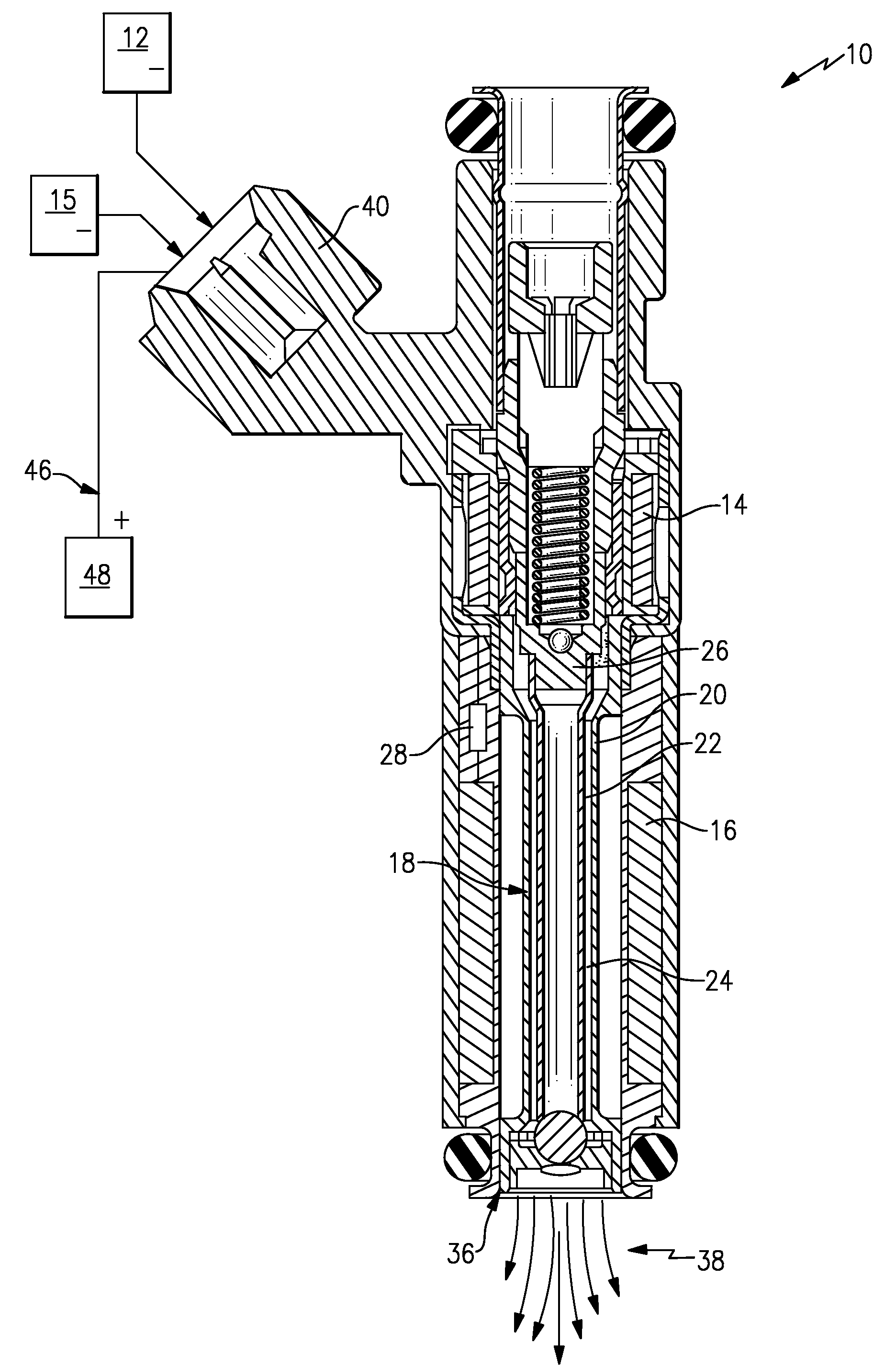
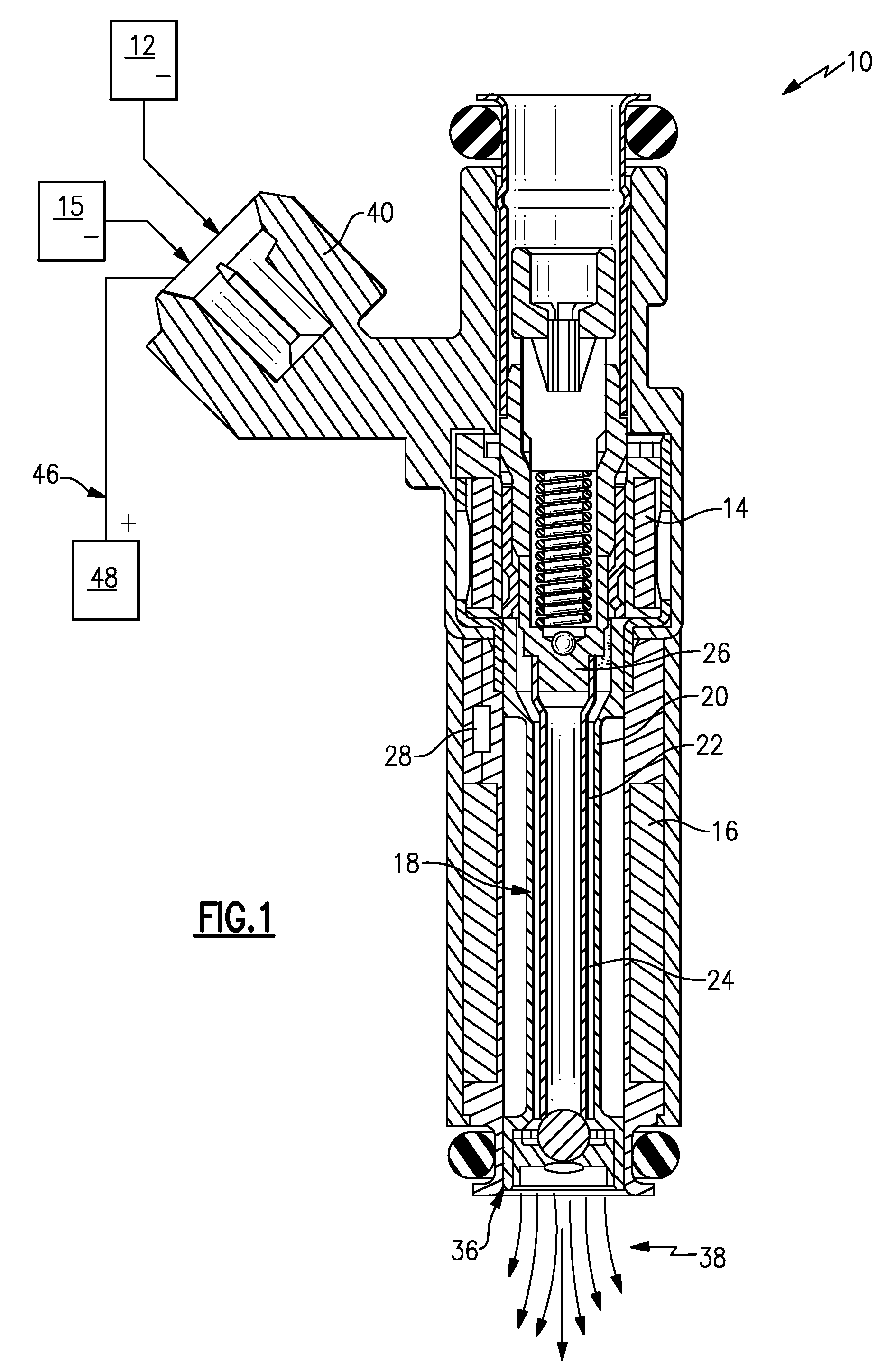
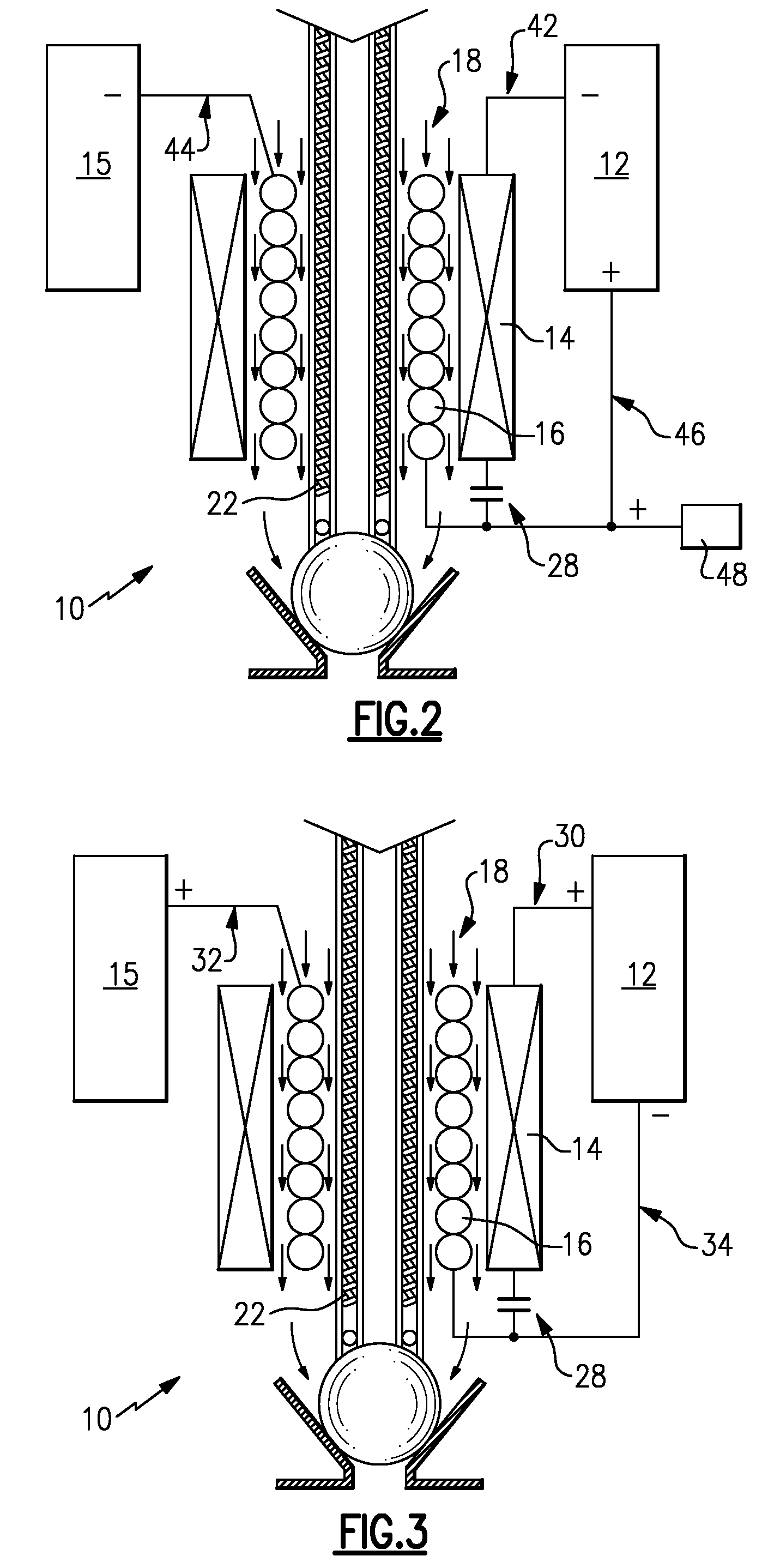
[0015]Referring to FIG. 1, an example fuel injector 10 includes an annular fuel flow path 24 defined between an armature 26 and a valve body 20. The armature 26 moves within the valve body 20 between an open and closed position to regulate fuel flow 18 through the annular flow path 24. A first coil 14 receives a first signal from a direct current (DC) driver 12 to generate a first magnetic field that moves the armature 26 between the open and closed positions. A second coil 16 generates a second magnetic field that is utilized to heat a component in thermal contact with the fuel flow 18 that in turn heats fuel before exiting the fuel injector 10 through the outlet 36. The heated fuel exiting the outlet 36 as indicated at 38 is raised to a temperature that substantially vaporizes the liquid fuel to achieve a high level of atomization that in turn improves combustion performance.

[0016]The component in thermal contact with the fuel flow 18 in this example is an armature tube 22 of the ...


PUM


Abstract

A fuel injector assembly includes a first coil driven by a direct current driver and a second coil driven by an alternating current driver where both the first coil and the second coil share a common connection to reduce the number of external terminal connections. The second coil generates a second magnetic field that is utilized to heat a component in thermal contact with the fuel flow that in turn heats fuel before exiting the fuel injector.

Description

CROSS REFERENCE TO RELATED APPLICATION[0001]The application claims priority to U.S. Provisional Application No. 60 / 784,697 which was filed on Mar. 22, 2006.BACKGROUND OF THE INVENTION[0002]This invention generally relates to a fuel injector for a combustion engine. More particularly, this invention relates to a fuel injector that heats fuel to aid the combustion process.[0003]Combustion engine suppliers continually strive to improve emission and combustion performance. One method of improving both emission and combustion performance includes heating or vaporizing fuel before injection into the combustion chamber. Heating the fuel replicates operation of a hot engine, and therefore improves combustion performance. Further, alternate fuels such as ethanol perform poorly in cold conditions, and therefore also benefit from pre-heating of fuel.[0004]Various methods of heating fuel at a fuel injector have been attempted. Such methods include the use of a ceramic heater, or a resistively h...

Claims


Application Information

Patent Timeline
IPC IPC(8): F02M47/02F02M63/00F02M51/00
CPCF02M53/06F02M51/0682
Inventor HORNBY, MICHAEL J.NALLY, JOHN F.SAYAR, HAMIDCZIMMEK, PERRY ROBERT
Owner VITESCO TECH USA LLC
Why Eureka
Try Eureka