Latching apparatus and method

Inactive Publication Date: 2007-09-27
CORNWELL CARL R
View PDF26 Cites 17 Cited by
  • Summary
  • Abstract
  • Description
  • Claims
  • Application Information

AI Technical Summary

Benefits of technology

[0012] An advantage of the present invention is the ability to connect and disconnect quickly and safely. Another advantage is that the present apparatus can offload equipment from floating vessels. Still yet another advantage is that the receptacle can be latched onto the prong without the need to have a person directly operating the latch. In other words, the apparatus can be lowered from a platform on a cable, and the prong can be attached to a container on a boat deck, and due to the design, the receptacle can be latched onto the prong by having the crane operator lower the skirt onto the prong without having an individual on the deck of the boat. Stil

Problems solved by technology

As those of ordinary skill in the art will recognize, the seas can get quite rough.
As those of ordinary skill in the art will recognize, attaching the ball hook onto the slings is a dangerous endeavor since the boat may be rocking due to wind and/or wa

Method used


Image

  • Latching apparatus and method
  • Latching apparatus and method
  • Latching apparatus and method

Examples


Embodiment Construction

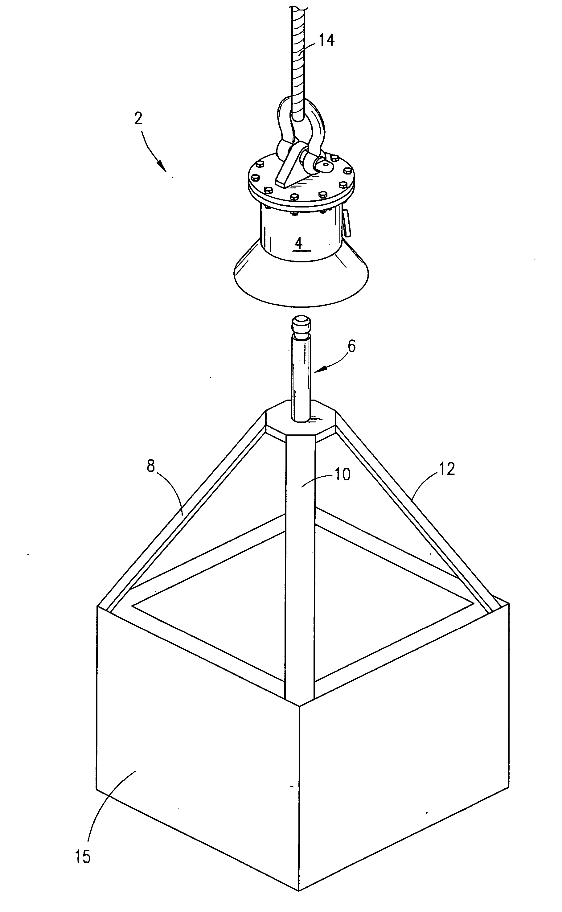
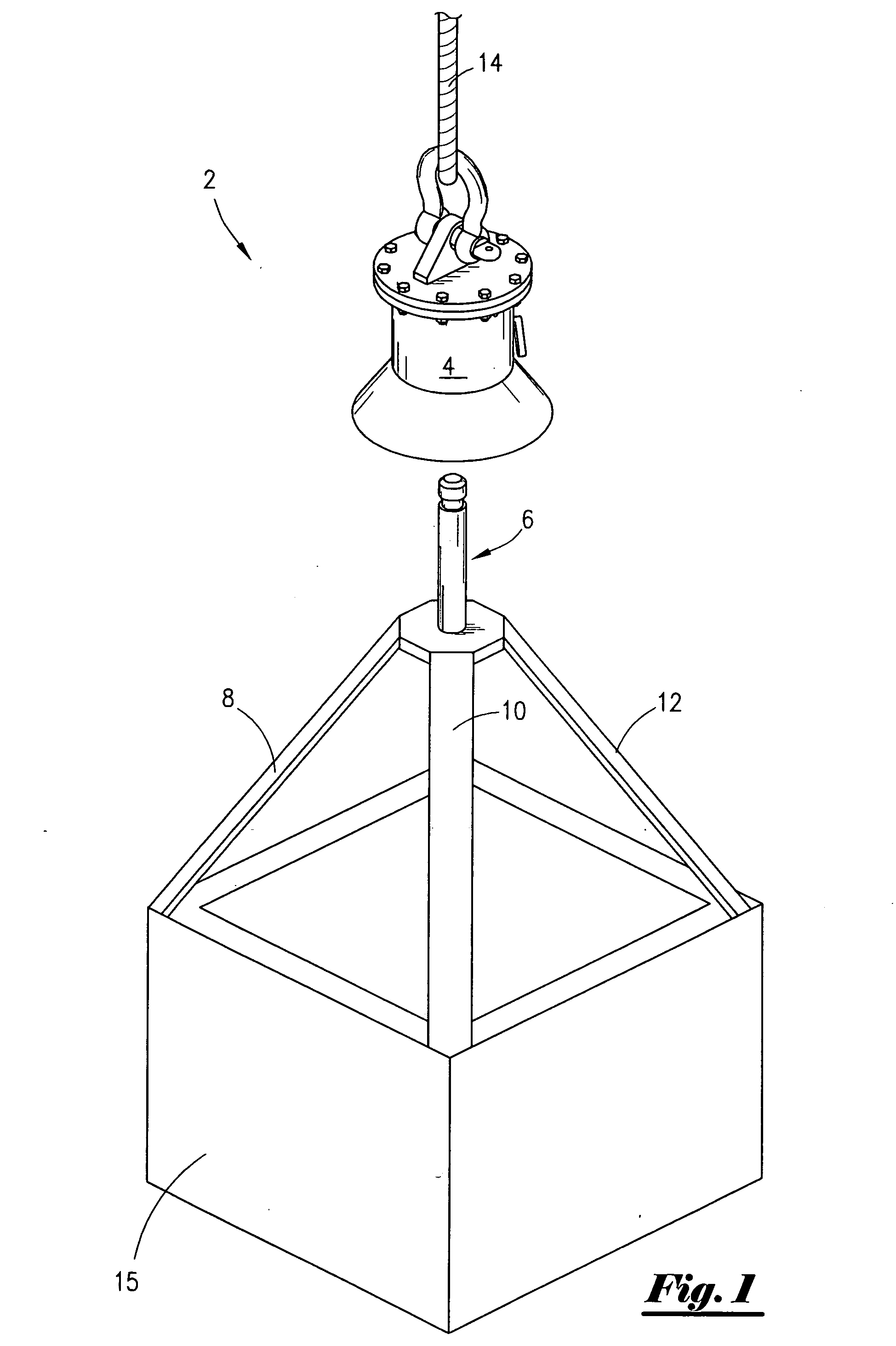
[0028]FIG. 1 illustrates a perspective view of the most preferred embodiment of the latching mechanism 2 that includes the receiving receptacle 4 and the prong 6. FIG. 1 further illustrates the support members 8, 10, 12 that will be connected to a container 15. The receiving receptacle 4 is being lowered via cable 14 that is connected to a shackle.

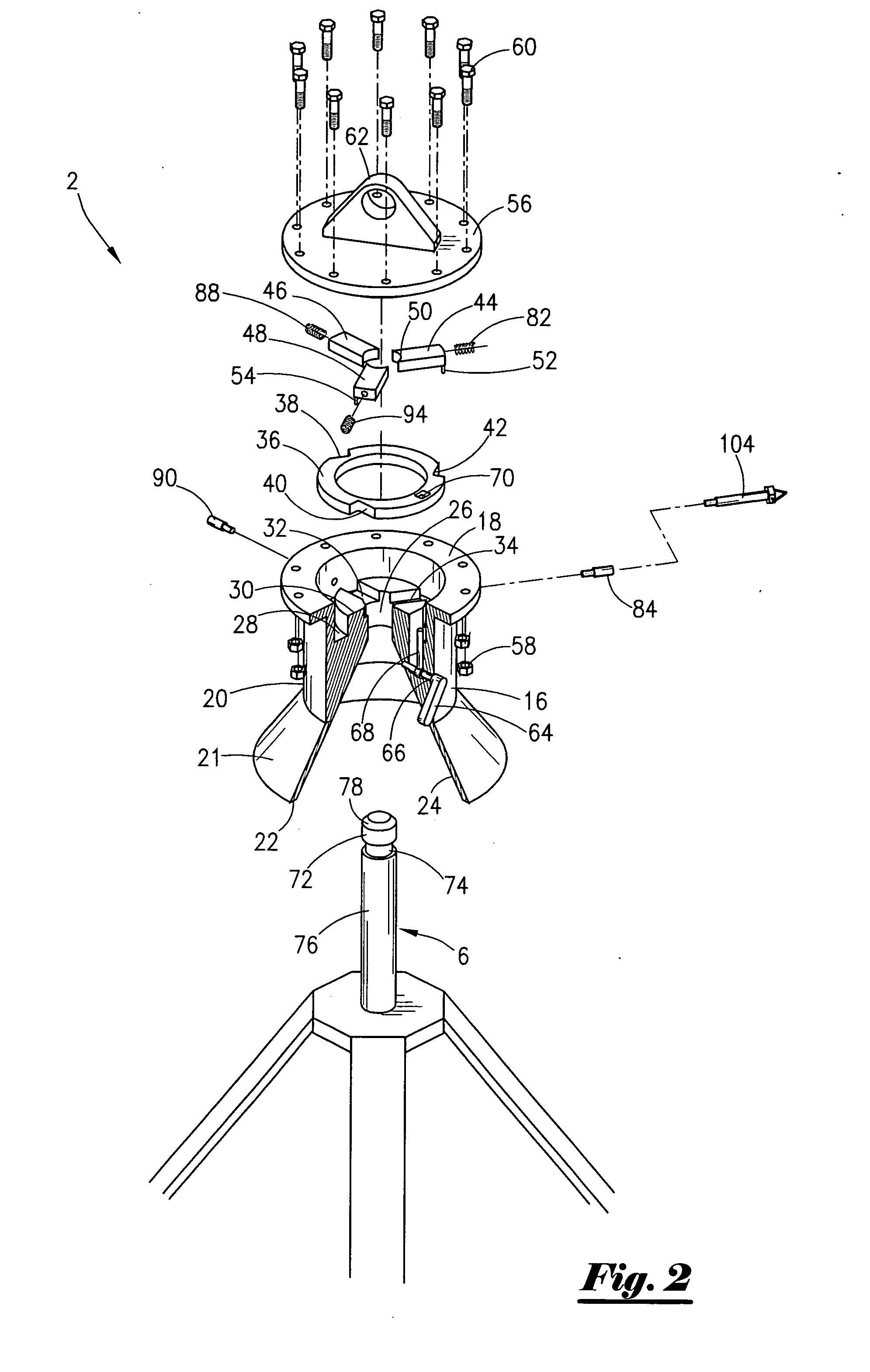
[0029] Referring now to FIG. 2, an exploded view of the most preferred embodiment of the latching mechanism 2 will now be described. FIG. 2 depicts the body 16, wherein the body includes a flange end 18 that extends to a cylindrical body 20 that in turn extends to the conically shaped outer surface 21 which in turn terminates at the radial end 22. Extending radially inward is the conically shaped inner surface 24, and wherein the conically shaped inner surface 24 may be referred to as the funnel 24. The funnel 24 extends to the central bore passage 26.

[0030] As seen in FIG. 2, the flanged end 18 extends radially inward to a groove sectio...


PUM


Abstract

A latching apparatus for lifting and lowering loads. The apparatus comprises a prong and a receiving receptacle configured to receive the prong. The receiving receptacle comprises a body having a central passage, a plurality of jaws arranged about the central passage, and a spring for biasing the jaws to extend into the central passage. The latching apparatus may further comprise an activation disc for disengaging the jaws from the prong. The jaws have a pin extending therefrom; and wherein the activation disc contains a plurality of cam surfaces that engage the pin of the jaws. A method of latching onto a container is also disclosed.

Description

BACKGROUND OF THE INVENTION [0001] This application relates to a latching mechanism. More specifically, but not by way of limitation, this invention relates to a latching mechanism for lifting and lowering containers. [0002] In industrial applications, operators find it necessary to lift containers. Many times, the containers are located in remote areas. For instance, in the offshore energy industry, boats ferry equipment to platforms located many miles from shore. As those of ordinary skill in the art will recognize, the seas can get quite rough. Generally, the containers will be positioned on the aft deck of the boat. In order to offload the equipment, a platform crane is used to lift the containers from the boat deck onto the platform. [0003] Prior art devices requires the use of a ball hook, which is attached to the cable. A deck hand is required to attached the ball hook onto the containers. Sometimes, the ball hook is attached to a set of slings. As those of ordinary skill in ...

Claims


Application Information

Patent Timeline
IPC IPC(8): B66C1/62
CPCB66C1/62
Inventor CORNWELL, CARL
Owner CORNWELL CARL R
Why Eureka
Try Eureka