
Vehicle driving force control apparatus

a technology of driving force and control apparatus, which is applied in the direction of ab control system, braking system, etc., can solve problems such as unstable vehicle behavior, and achieve the effect of reducing the total braking force acting on the vehicle and increasing the speed of the vehicl

Inactive Publication Date: 2007-09-27
NISSAN MOTOR CO LTD
View PDF2 Cites 20 Cited by
  • Summary
  • Abstract
  • Description
  • Claims
  • Application Information

AI Technical Summary

Benefits of technology

The present invention provides a driving force control apparatus that can prevent the vehicle speed from increasing when the wheels are released from being locked. The apparatus includes a driving force distribution control unit, a wheel speed detection unit, a vehicle speed detection unit, a braking force control unit, and a distribution ratio changing unit. The driving force distribution control unit is configured to distribute a driving force to a plurality of wheels of a vehicle based on a preset distribution ratio. The wheel speed detection unit is configured and arranged to detect a rotational speed of at least one of the wheels. The vehicle speed detection unit is configured and arranged to detect a traveling speed of the vehicle. The braking force control unit is configured to apply a braking force to at least one of the wheels when the traveling speed that was detected exceeds a preset traveling speed. The distribution ratio changing unit is configured to change from the preset distribution ratio to an adjusted distribution ratio which increases the driving force of the wheels being braked by the braking force control unit that have reached or fallen below a preset minimum rotational speed threshold.

Problems solved by technology

Thus, the vehicle may behave in an unstable manner while the wheels are locked if the vehicle is descending down a steep slope.

Method used


Image

  • Vehicle driving force control apparatus
  • Vehicle driving force control apparatus
  • Vehicle driving force control apparatus

Examples


first embodiment

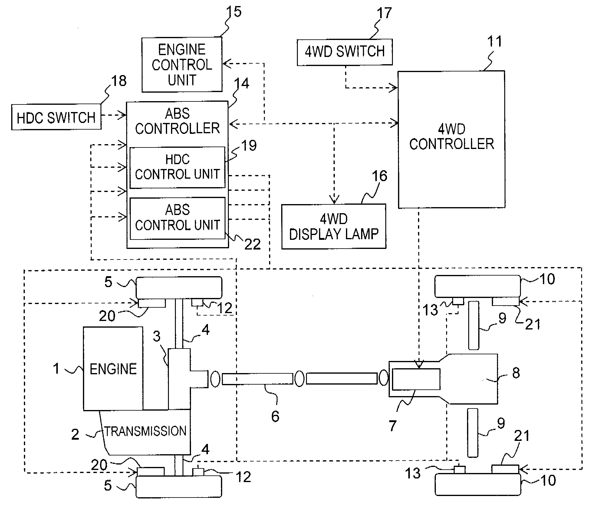
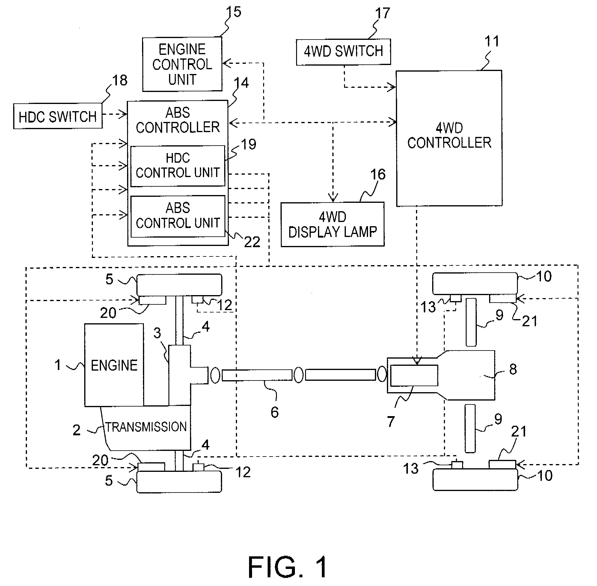
[0019]Referring initially to FIG. 1, a schematic block diagram of a four-wheel drive vehicle is illustrated that is equipped with a driving force control apparatus in accordance with the present invention. Basically, the drive system of the four-wheel drive vehicle includes, among other things, an engine 1, a transmission 2, a differential gear 3, a pair of front drive shafts 4, a pair of front (main drive) wheels 5, a propeller shaft 6, a coupling 7, a rear final drive 8, a pair of rear drive shafts 9 and a pair of rear (auxiliary drive) wheels 10. The engine 1 is disposed toward the front wheels 5. The drive force of the engine 1 is transmitted to the front wheels 5, which are the main drive wheels, via the transmission 2, the differential gear 3 and the front drive shafts 4. The drive force is also transmitted to the rear wheels 10, which are auxiliary drive wheels, via the transmission 2, the differential gear 3, the propeller shaft 6, the coupling 7, the rear final drive 8, and...

second embodiment

[0058]FIG. 4 is a flowchart showing the control process executed by the ABS controller 14 of the driving force distribution control apparatus in accordance with the present invention. This flowchart is repeated at specific intervals when the HDC switch is “on”.

[0059]The process starts in step S41. In step S42, the state of the accelerator as operated by the driver is detected, and if the acceleration pedal is not depressed (accelerator OFF), then the process advances to step S43. In step S43, the state of the brakes (e.g., the brake units 20 and 21) as operated by the driver is detected, and if the brake pedal is not depressed (brake OFF), then the process advances to step S44. However, if either the acceleration pedal or the brake pedal is being operated, then the process advances to step S60, and the control ends. Thus, steps S42 and S43 are equivalent to the step S2 of the first embodiment.

[0060]In step S44, a confirmation is made as to whether a distribution ratio variation flag...


PUM


Abstract

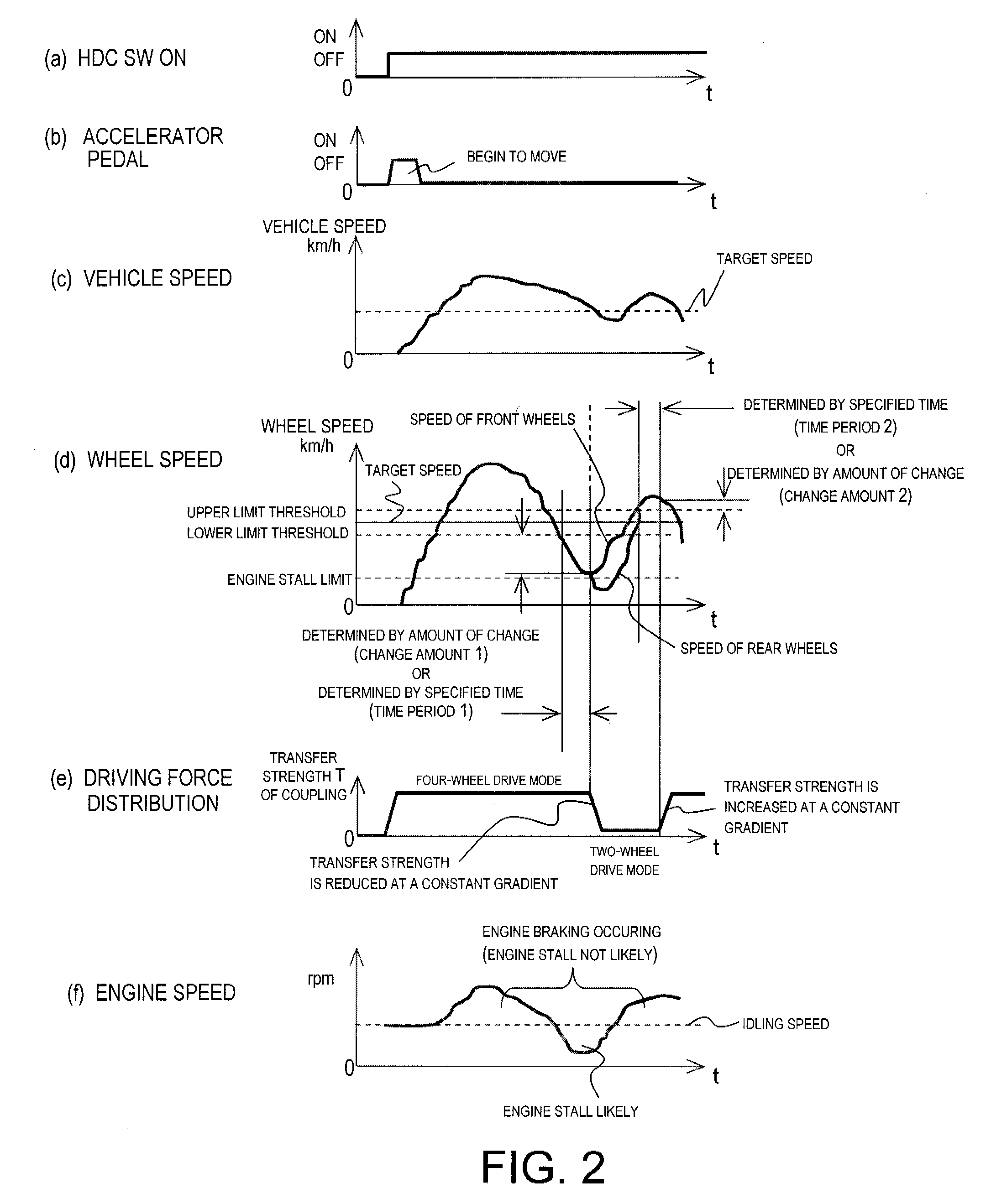
A driving force control apparatus is configured to automatically apply a braking force to a plurality of wheels in order to descend down a hill at a constant speed, such that the wheels can be prevented from being locked by the braking force, and the vehicle speed can be prevented from increasing. In order for a vehicle to travel at a preset speed, the vehicle driving force control apparatus detects the speeds of the wheels subjected to a braking force, and switches the vehicle from a four-wheel drive (4WD) mode in which driving force is distributed to all of the wheels to a two-wheel drive (2WD) mode in which driving force is distributed to only the front wheels. The switch is made when the vehicle speed is equal to or less than a lower limit threshold. The front wheels are prevented from locking, and increases in the vehicle speed are suppressed.

Description

CROSS-REFERENCE TO RELATED APPLICATIONS[0001]This application claims priority to Japanese Patent Application No. 2006-052523, filed on Feb. 28, 2006 and Japanese Patent Application No. 2007-036350, filed on Feb. 16, 2007. The entire disclosures of Japanese Patent Application Nos. 2006-052523 and 2007-036350 are hereby incorporated herein by reference.BACKGROUND OF THE INVENTION[0002]1. Field of the Invention[0003]The present invention generally relates to a driving force control apparatus used in a vehicle. More specifically, the present invention relates to a driving force control apparatus that varies the drive / braking force to the wheels to decelerate the vehicle until a preset constant speed is reached and to prevent the wheels from locking up when the vehicle is descending down a hill or the like.[0004]2. Background Information[0005]In the past, it has been proposed that vehicles be equipped with an HDC function (Hill Descent Control) that enables the vehicle to slowly descend ...

Claims


Application Information

Patent Timeline
Patent Type & Authority Applications(United States)
IPC IPC(8): B60T8/32
CPCB60T8/1766B60T8/1769B60W10/184B60T2270/12B60W10/119B60T2201/04
Inventor FUKUDA, YOSHIYUKIANDO, MASAMICHI
Owner NISSAN MOTOR CO LTD
Learn More