Motor

a motor and motor body technology, applied in the field of motors, can solve the problems of increasing manufacturing costs, and achieve the effect of convenient molded

Inactive Publication Date: 2007-09-27
SANKYO SEIKI MFG CO LTD
View PDF12 Cites 15 Cited by
  • Summary
  • Abstract
  • Description
  • Claims
  • Application Information

AI Technical Summary

Benefits of technology

[0015]In view of the problems described above, an embodiment of the present invention may adv...

Problems solved by technology

Moreover, in the case when a ring-shaped injection gate is used, a die structure becomes to be complicated...

Method used


Image

  • Motor
  • Motor
  • Motor

Examples


Embodiment Construction

[0047]A motor in accordance with an embodiment of the present invention is applied to a stepping motor provided with a lead screw, which will be described below with reference to the accompanying drawings. The motor in accordance with the present invention is not limited to a stepping motor.

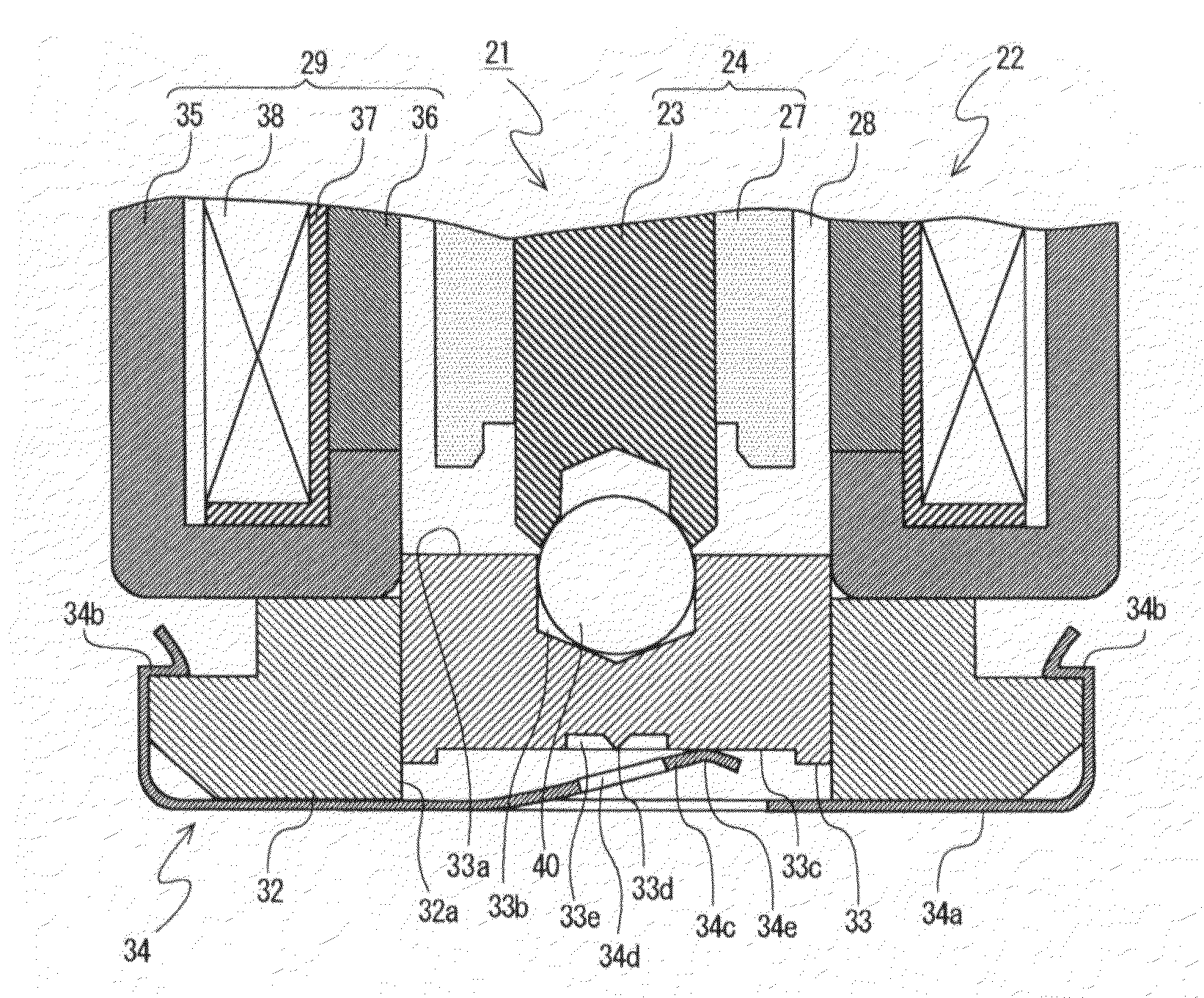
[0048]FIG. 7 is a side view showing a stepping motor with a lead screw as a motor in accordance with an embodiment of the present invention. FIG. 8 is a front view showing a stepping motor with a lead screw as a motor in accordance with an embodiment of the present invention. FIG. 1 is a cross-sectional view showing a part of a stepping motor with a lead screw as a motor in accordance with an embodiment of the present invention.

[0049]In FIGS. 1, 7 and 8, a motor 21 includes a stator 22, a rotor 24 having a rotor shaft 23 whose one end is held in an inside of the stator 22, and a bracket 26 formed in a “U”-shape in cross section which is fixed to the stator 22 and supports the other end of the rot...


PUM


Abstract

A motor may include a bearing made of resin for rotatably supporting one end part of the rotor shaft, and an urging member attached to a bearing holder and abutted with a pressurization face of the bearing to urge the bearing toward a side of the rotor shaft. A molding material injection gate trace (projection) which has been used when the bearing is resin-molded is positioned at a center portion of the pressurization face. The molding material injection gate trace may be positioned in a recessed part which is formed at a roughly center portion of the pressurization face of the bearing. Further, the urging member may include an urging piece which is formed by cutting a center portion of a metal plate in a ring shape and an opening part is formed in the urging piece.

Description

CROSS REFERENCE TO RELATED APPLICATION[0001]The present invention claims priority under 35 U.S.C. §119 to Japanese Application No. 2006-78530 filed Mar. 22, 2006, which is incorporated herein by reference.FIELD OF THE INVENTION[0002]An embodiment of the present invention may relate to a motor. More specifically, an embodiment of the present invention may relate to a structure of a bearing for supporting a shaft end of a rotor shaft and / or an urging member for urging the bearing to the rotor shaft.BACKGROUND OF THE INVENTION[0003]A conventional stepping motor 1, for example, as shown in FIG. 9 which is used for driving a lens in a digital camera, a digital video camera and the like has been known.[0004]The motor 1 shown in FIG. 9 includes a stator 2 and a rotor 4 which is disposed on an inner side of the stator 2 and provided with a rotor shaft 3.[0005]The stator 2 holds a bobbin 7 with an outer yoke 5 and an inner yoke 6. A winding wire 8 is wound around the bobbin 7.[0006]A rotor m...

Claims


Application Information

Patent Timeline
IPC IPC(8): H02K1/04H02K5/16H02K1/12
CPCF16C17/08F16C2380/27H02K5/1672F16C27/08
Inventor SONOHARA, HIROYUKIMIYASHITA, TAKEYOSHI
Owner SANKYO SEIKI MFG CO LTD
Why Eureka
Try Eureka