Insulation structure of rotary electrical machinery

a technology of rotary electrical machinery and insulation structure, which is applied in the direction of dynamo-electric machines, dynamo-electric components, magnetic circuit shapes/forms/construction, etc., can solve the adverse effects of stress on the permanentity of the insulator 110, and achieve the expansion of the area capable of running continuously, efficient radiation of heat generated in the winding, and improved cooling effect of the rotary electrical machinery

Inactive Publication Date: 2007-09-27
HONDA MOTOR CO LTD
View PDF3 Cites 53 Cited by
  • Summary
  • Abstract
  • Description
  • Claims
  • Application Information

AI Technical Summary

Benefits of technology

[0031]According to the present invention, a stator having exceptional insulation and heat radiation (cooling effect) can be constituted. As a result, the heat generated in the winding can be efficiently radiated, so that the cooling effect of the rotary electrical machinery can be improved and the area capable of running continuously can be expanded.
[0032]In addition, since the temperature of the winding can be decreased, the electrical resistance and the copper loss can be reduced.
[0033]Furthermore, the high-heat-conductive electrical-insulation resin sheet is disposed between the teeth and the insulator at the superposition portion at which the insulator and the high-heat-conductive electrical-insulation resin sheet are stacked. Therefore, the insulator does not rattle: and oscillations and noise can be prevented.
[0034]According to the present invention, the stress applied to the side wall of the insulator can be reduced at the superposition portion. Therefore, the permanence of the insulator can be improved, and the life span of the rotary electrical machinery can be increased.
[0035]According to the present invention, a stator and rotary electrical machinery having exceptional insulation, permanence, and productivity can be constructed.
[0036]According to the present invention, the insulation range between the winding and the iron core (teeth) can be set appropriately.

Problems solved by technology

The permanence of the insulator 110 is adversely affected by use under stress.

Method used


Image

  • Insulation structure of rotary electrical machinery
  • Insulation structure of rotary electrical machinery
  • Insulation structure of rotary electrical machinery

Examples


Embodiment Construction

[0048]An embodiment of an insulation structure of rotary electrical machinery according to the present invention will explained below referring to FIGS. 1 to 8. The rotary electrical machinery in this embodiment is an aspect of a driving electric motor for a hybrid vehicle.

[0049]FIG. 7 is a perspective view showing an electric motor 1 in a state of a housing being detached therefrom. The electric motor is provided with a stator 2 and a rotor 4 rotating inside of the stator 2.

[0050]The explanation of the rotor 4 is omitted since it is not an essential point of the present invention. However, the stator 2 will be explained in detail. Hereinafter, “axial direction” in this description means the same direction as the axial direction of the stator 2 and the rotor 4.

[0051]The stator 2 is constructed by connecting a plurality of stator pieces 3 into a ring-shape. The single 8 prior to connecting into the ring shape is shown in FIG. 8.

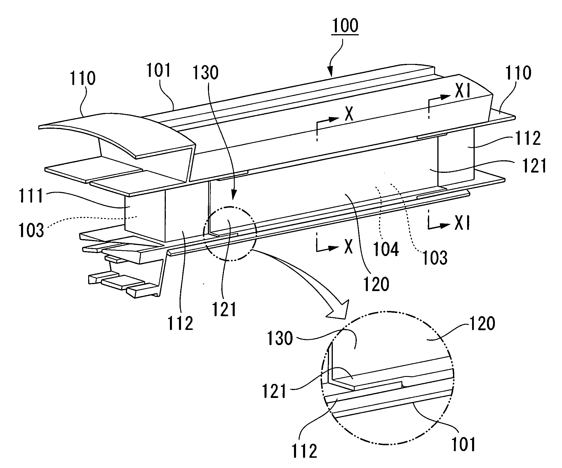
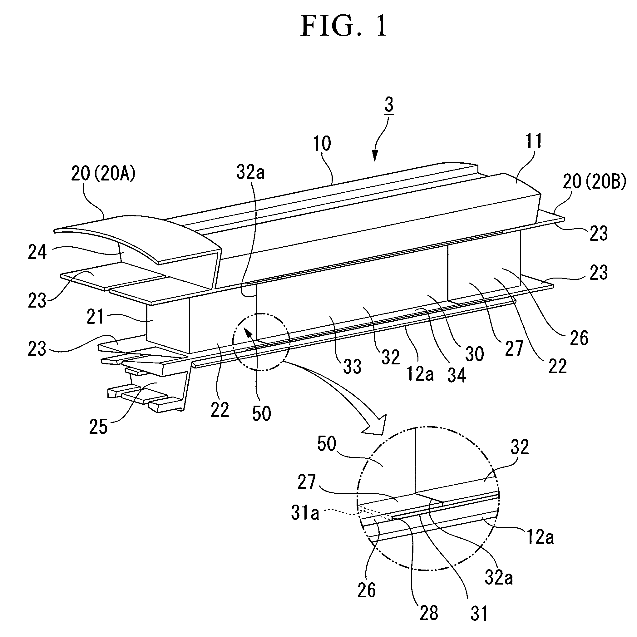
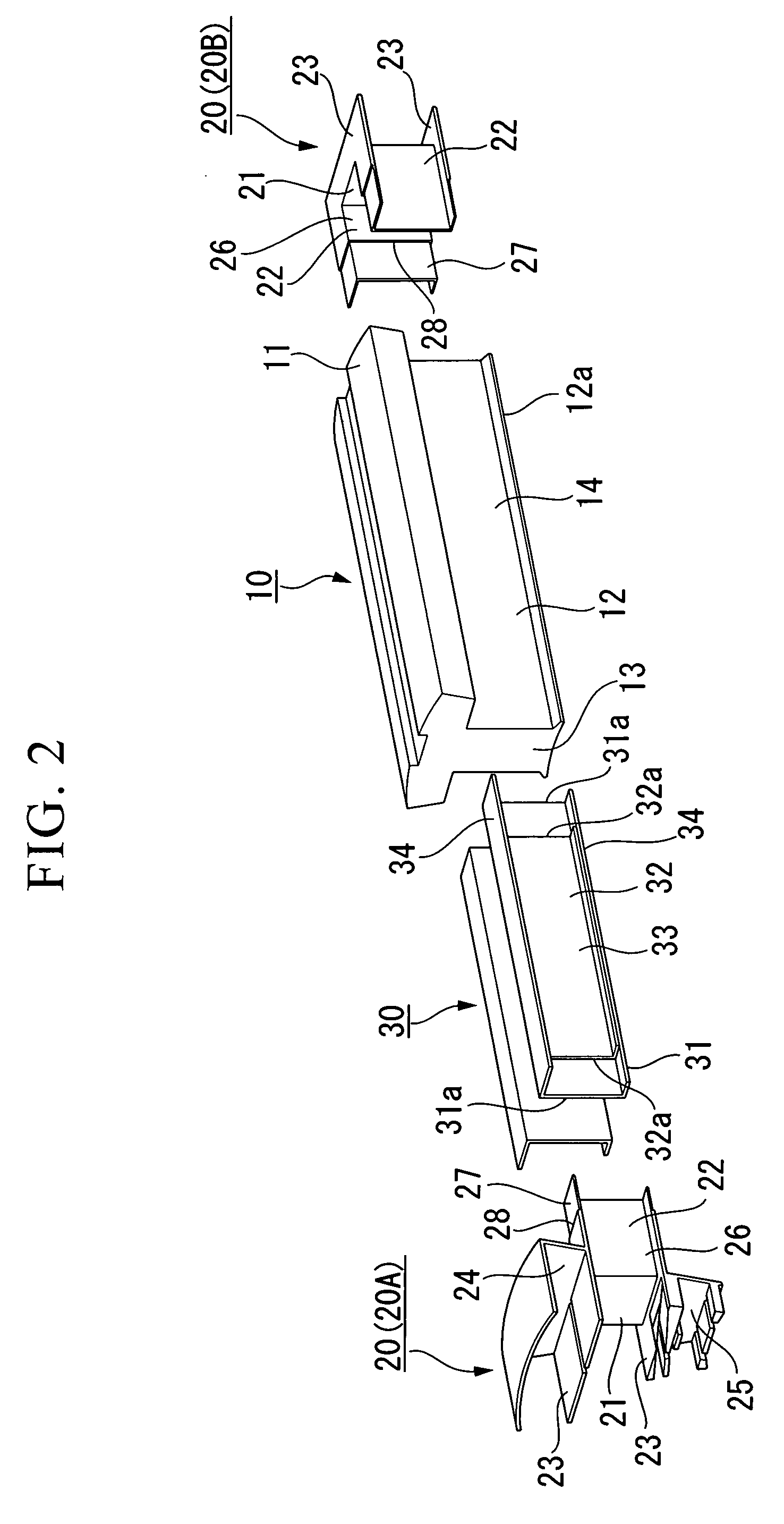
[0052]The stator piece 3 is provided with a split iron c...


PUM


Abstract

An insulation structure of rotary electrical machinery which electrically insulates teeth of a stator from a winding wound on the teeth includes: an insulator made from hard insulation material, disposed on both axial ends of the teeth, and having a side wall disposed along a side surface of the teeth crossing to a circumferential direction thereof, and a high-heat-conductive electrical-insulation resin sheet disposed along the side surface of the teeth and insulating the teeth from the winding, wherein an axial end portion of the high-heat-conductive electrical-insulation resin sheet is disposed between the side wall of the insulator and the side surface of the teeth and is stacked on the side wall in a prescribed axial extent.

Description

BACKGROUND OF THE INVENTION[0001]1. Field of the Invention[0002]This invention relates to an insulation structure of a rotary electrical machinery such as electric motors or electric generators.[0003]Priority is claimed on Japanese Patent Application No. 2006-082474, filed Mar. 24, 2006, the contents of which are incorporated herein by reference.[0004]2. Description of Related Art[0005]In stators of rotary electrical machinery such as electric motors or electric generators, electrical insulation between an iron core and a winding of the stator is needed. For example, in an electric motor of Japanese Unexamined Patent Application, First Publication No. 2001-112205, teeth are electrically insulated from a winding by providing an insulator formed from a hard insulating material (e.g., a resin) at both ends of the axial direction of the teeth of an iron core, providing an insulating paper along the side surface of the teeth crossing the circumferential direction of the teeth, and provid...

Claims


Application Information

Patent Timeline
Patent Type & Authority Applications(United States)
IPC IPC(8): H02K3/34H02K1/12H02K3/46
CPCH02K3/522H02K2203/12H02K2203/06H02K9/22H02K9/223
Inventor FUKUI, KENTAROKABASAWA, AKIRA
Owner HONDA MOTOR CO LTD
Why Eureka
Try Eureka