
Battery jumper

a battery charger and battery technology, applied in the direction of electrochemical generators, coupling device connections, transportation and packaging, etc., can solve the problems of not being able to meet the needs of users, not being able to use cellular phones to their fullest extent, and being bulky in size, so as to achieve convenient charging of rechargeable batteries and compact size. , the effect of compact siz

Inactive Publication Date: 2007-09-27
SUPERIOR COMM
View PDF19 Cites 6 Cited by
  • Summary
  • Abstract
  • Description
  • Claims
  • Application Information

AI Technical Summary

Benefits of technology

[0007] A main object of the present invention is to provide a battery jumper for a battery, wherein the battery jumper has an extreme compact size for conveniently charging a rechargeable battery in a wide variety of circumstances.
[0008] Another object of the present invention is to provide a battery jumper for a battery, wherein the battery jumper comprises a resilient unit for preventing electric terminals of the battery and the battery jumper to be pressed too hard against each other so as to prevent mutual damage of the battery and the battery jumper. In other words, the present invention improves the general life-span of the battery.
[0009] Another object of the present invention is to provide a battery jumper for a battery, which is capable of forming a compact personal accessory, such as a key chain, for facilitating easy carrying and storage of the battery jumper. In other words, the present invention allows widespread application thereof.

Problems solved by technology

A main disadvantage of this conventional battery charger is that it is bulky in size and therefore is not generally portable.
As a consequence, cellular phones have not been utilized to their fullest extent.
Another disadvantage of conventional battery chargers is that the electric terminals of the battery chargers are usually pressed towards the electric terminals of the rechargeable batteries so as to ensure secure engagement between the electric terminals for allowing that the recharging process can be successfully accomplished.
The problem here is that when the electric terminals are pressed too hard, each of the electric terminals will cause mutual damage to each other (i.e. the electric terminals of the battery chargers may cause mutual damage to the electric terminals of the rechargeable batteries) so that the general life-span of both the battery chargers and the rechargeable batteries will be substantially reduced.
Very often, the cost of buying a new rechargeable battery is substantial when compared to the overall price of buying a new cellular phone.
Moreover, when a particular model of cellular phone is outdated, the manufacturer may no longer manufacture the corresponding rechargeable battery so that the user may not be able to purchase a new rechargeable battery.

Method used


Image

  • Battery jumper
  • Battery jumper
  • Battery jumper

Examples


Embodiment Construction

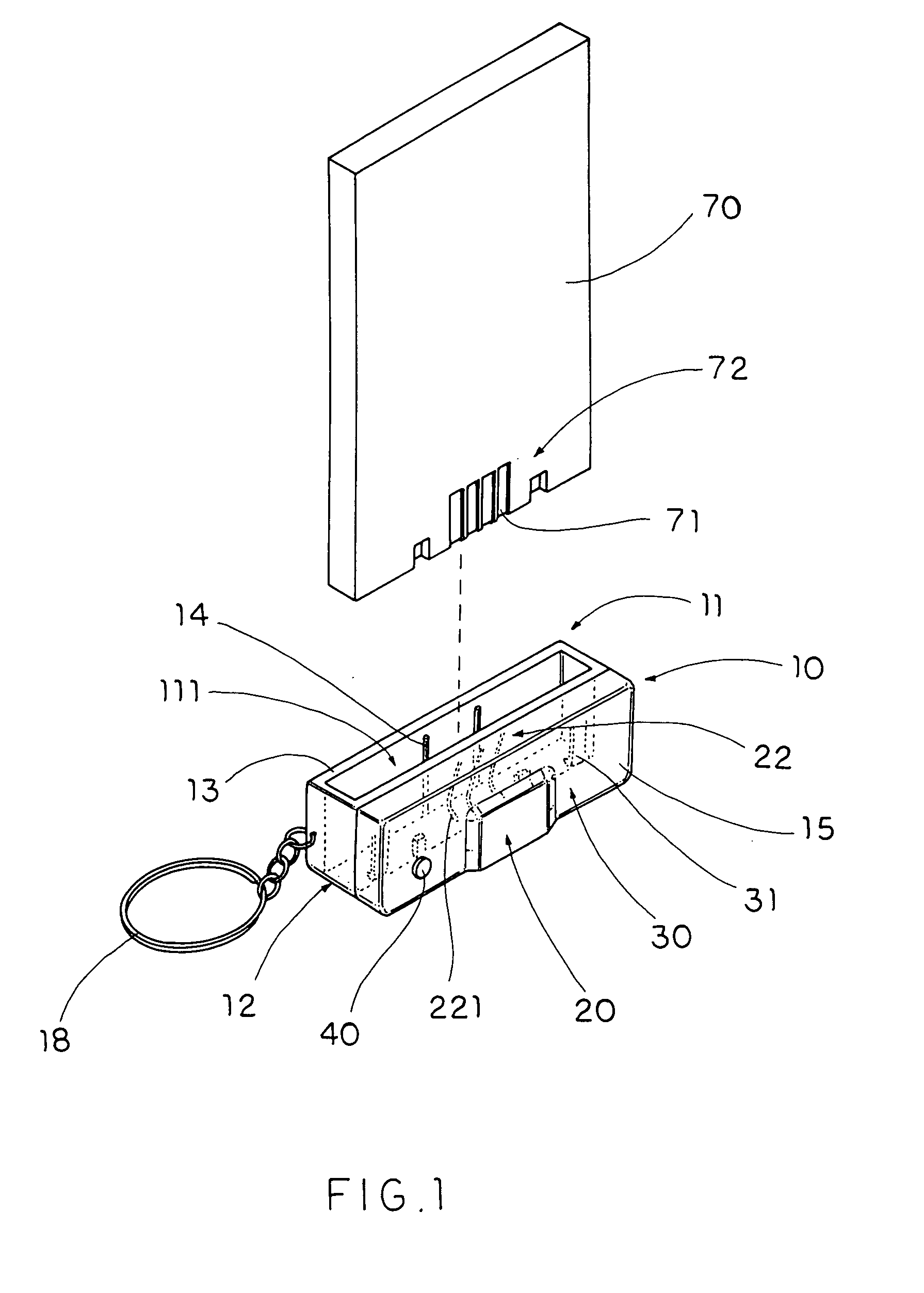
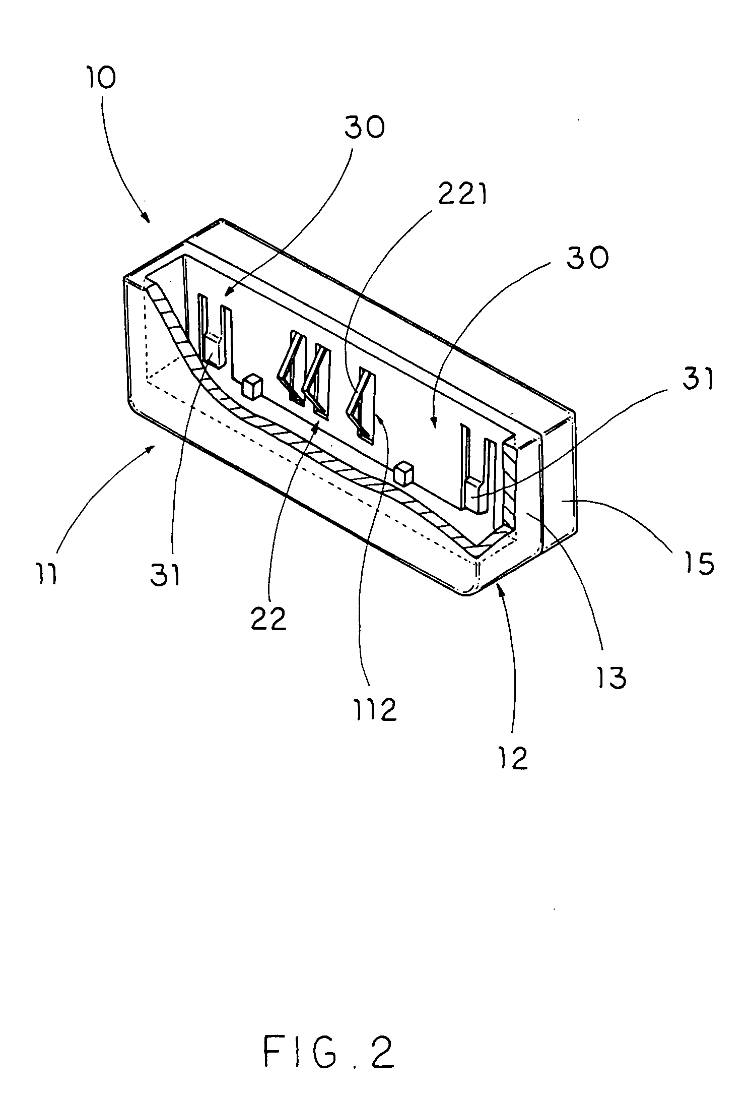
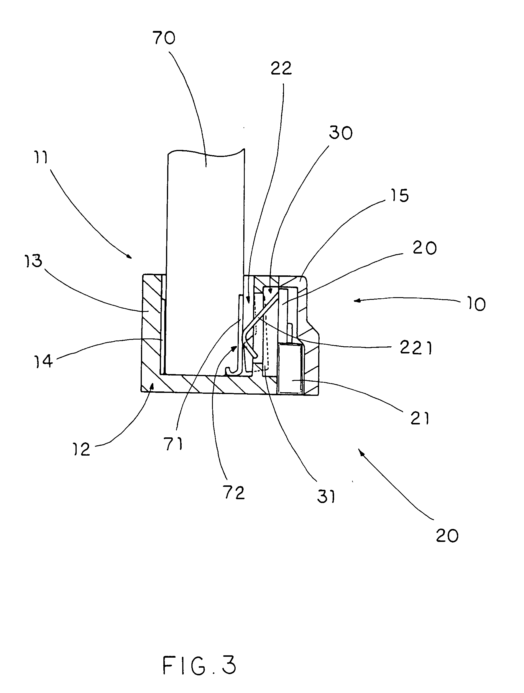
[0024] Referring to FIG. 1 to FIG. 3 of the drawings, a battery jumper for a battery 70 having a battery terminal 71 provided at a terminal side edge 72 thereof according to a preferred embodiment of the present invention is illustrated, in which the battery jumper comprises a battery station 10, a recharging circuit 20, and a resilient unit 30.

[0025] The battery station 10 has a battery shoe 11 adapted for coupling the terminal side edge 72 of the battery 70 to retain the battery 70 in position.

[0026] The recharging circuit 20 comprises a power inlet 21 adapted for electrically connecting with a power source, and a charging terminal 22 supported at the battery shoe 11 for contacting with the battery terminal 71 of the battery 70 to recharge the battery 70.

[0027] The resilient unit 30 is supported at the battery shoe 11 for applying a pushing force against the terminal side edge 72 of the battery 70 to minimize a pressure of the charging terminal 22 against the battery terminal 7...


PUM


Abstract

A battery jumper for a battery having a battery terminal at a terminal side edge thereof includes a battery station, a recharging circuit, and a resilient unit. The battery station has a battery shoe adapted for coupling the terminal side edge of the battery to retain the battery in position. The recharging circuit includes a power inlet adapted for electrically connecting with a power source, and a charging terminal supported at the battery shoe for contacting with the battery terminal of the battery to recharge the battery. The resilient unit is supported at the battery shoe for applying a pushing force against the terminal side edge of the battery to minimize a pressure of the charging terminal against the battery terminal of the battery.

Description

BACKGROUND OF THE PRESENT INVENTION [0001] 1. Field of Invention [0002] The present invention relates to a rechargeable battery, and more particularly to a battery jumper having an extreme compact size for conveniently charging a rechargeable battery in a wide variety of circumstances. [0003] 2. Description of Related Arts [0004] A conventional battery charger usually comprises a charger station and a power adapter for charging a rechargeable battery, such as a rechargeable battery for a cellular phone or a digital camera. The charger station usually comprises a charger base having a disposing cavity formed thereon and a plurality of charging terminals provided on the disposing cavity for aligning with an electric terminal of the rechargeable battery, a recharging circuitry provided in the charger base and electrically connecting the charging terminals with the power adapter which is further connected with an external power source for charging the rechargeable battery. [0005] A main...

Claims


Application Information

Patent Timeline
IPC IPC(8): H02J7/00
CPCH01M10/46H01R31/065H01R13/627H01R13/24Y02E60/10
Inventor CHEN, SOLOMON
Owner SUPERIOR COMM
Learn More