Display device for telescope system

a technology for telescopes and display devices, applied in telescopes, instruments, optics, etc., can solve the problems of variable image size of electronic signals, inability to achieve high magnification ratios, and inability to adjust magnification ratios, etc., to achieve constant image size and brightness

Active Publication Date: 2007-09-27
ASIA OPTICAL INT LTD
View PDF3 Cites 6 Cited by
  • Summary
  • Abstract
  • Description
  • Claims
  • Application Information

AI Technical Summary

Benefits of technology

[0008]Accordingly, an object of the present invention is to provide a display device for a telescope system that effectively solves the conventional problems of image size and brightness variation, and image position shift of the electronic signal with magnification variation. By using the present display device for a telescope system, constant image size and brightness of the displayed electronic signal can be maintained, and the electronic signal can also be imaged onto any position within the telescope field of view.

Problems solved by technology

This will result in variation of the image size of the electronic signal along with the magnification variation.
Consequently, the magnification ratio cannot be too high, normally below 3 times, otherwise the image size of the electronic signal will be too small in case of a lower magnification, or too large in case of a higher magnification.
This adversely affects vision feeling and electronic control.

Method used


Image

  • Display device for telescope system
  • Display device for telescope system
  • Display device for telescope system

Examples


Embodiment Construction

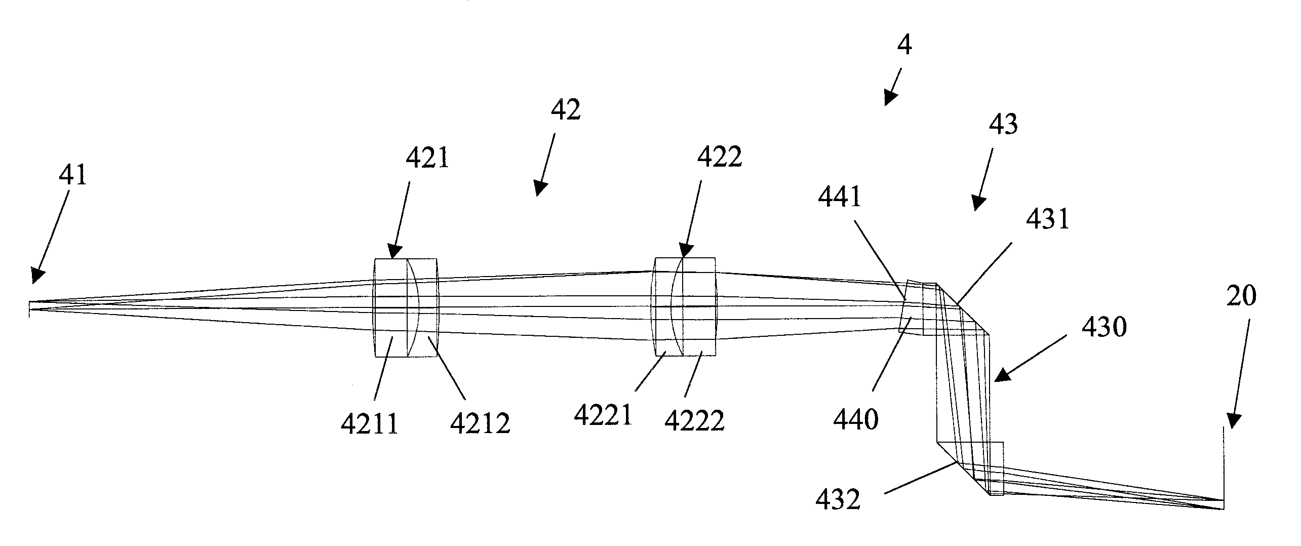
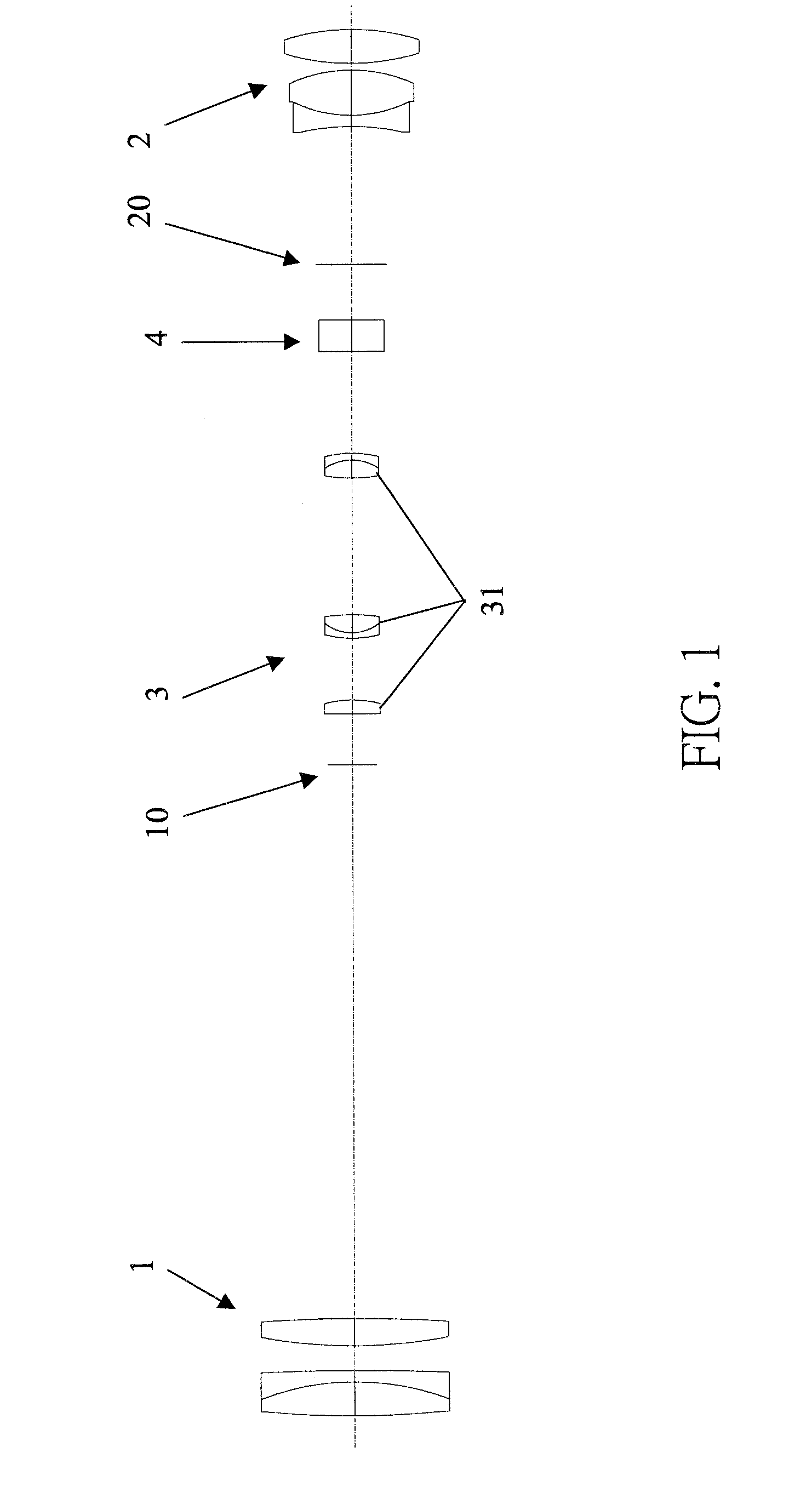
[0018]Referring to FIG. 1, a telescope system employing a display device 4 in accordance with the present invention includes an objective system 1, an eyepiece system 2, a magnification system 3 and the display device 4. The light reflected by the target to be observed is incident into the telescope system via the objective system 1, and is focused and imaged onto a first image plane 10 by the objective system 1. The light beam is further magnified and erected by the magnification system 3, and finally focused and imaged onto a second image plane 20 for observation by the observer through the eyepiece system 2. All the objective system 1, the eyepiece system 2 and the magnification system 3 may be of a conventional design, and thus a detailed description thereof is omitted herein. The display device 4 of the present invention is described in detail hereinafter.

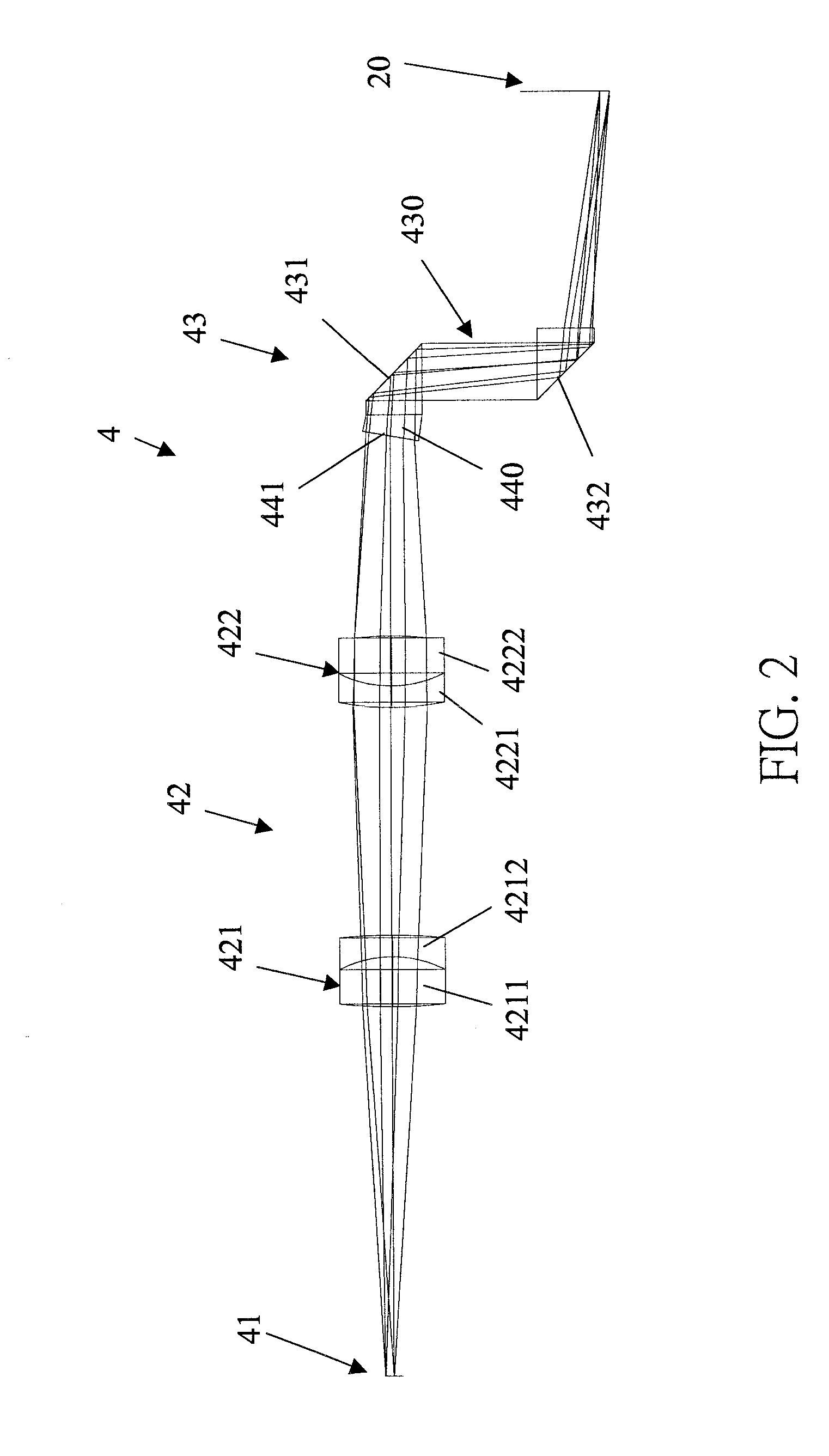
[0019]As shown in FIG. 2, the display device 4 is disposed between the first image plane 10 and the second image plane 20. I...


PUM


Abstract

A display device (4) for a telescope system is disposed between a first image plane (10) and a second image plane (20) of the telescope system. The display device includes a signal emitter (41), a converging lens group (42) positioned adjacent to the signal emitter, and a dioptric imaging lens group (43) positioned adjacent to the converging lens group. The optical signal emitted by the signal emitter is first transmitted through the converging lens group, then incident onto the dioptric imaging lens group, and finally imaged onto the second image after reflection of the dioptric imaging lens group. Therefore, both the image size and brightness of the displayed signal viewed by the observer can maintain unchanged in spite of the magnification variation of the telescope system.

Description

BACKGROUND OF THE INVENTION[0001]1. Field of the Invention[0002]The present invention relates to a display device for a telescope system, and particularly relates to a display device for a telescope system that has both range finding and electronic displaying functions[0003]2. Description of Prior Art[0004]The optical system of a conventional telescope or sight is generally composed of an objective, an image erecting lens group, an eyepiece and a scale board with a reticle. The scale board is marked with a rough rangefinding scale. By referring to the rangefinding scale, the observer can rapidly and roughly estimate the range to a target. Therefore, such a conventional telescope or sight may be used as a simple rangefinder.[0005]However, the range estimation by conventional telescope or sight is mostly dependent on the experience of the observer that may bring large tolerance. Accordingly, a laser telescopic sight progressively takes the place in the precise shooting and rangefindin...

Claims


Application Information

Patent Timeline
Patent Type & Authority Applications(United States)
IPC IPC(8): G02B23/00
CPCG02B23/02
Inventor LIAO, CHEN-CHEN
Owner ASIA OPTICAL INT LTD
Why Eureka
Try Eureka