Method and apparatus for alternatively switching between phone service lines

a technology of alternative switching and phone service, applied in the field of alternative switching between phone service lines, can solve the problems of damage to customer premise equipment, inability to enable services, and difficulty in providing an instantaneous cutover from one type of service (telco) to the new type of service (mso)

Inactive Publication Date: 2007-09-27
BOWERS MARK T +1
View PDF10 Cites 2 Cited by
  • Summary
  • Abstract
  • Description
  • Claims
  • Application Information

AI Technical Summary

Problems solved by technology

One of the main problems facing MSOs today is provisioning of the service.
Because different types of services are usually provided by two independent competing companies, such as the local telephone company and cable company, it is often difficult to provide an instantaneous cutover from one type of service (telco) to the new type of service (MSO).
Both services cannot be enabled at the same time (simultaneously connect both types of services to a common wire pair) because it is possible that damage would occur to customer premise equipment.
In addition, such provisioning would violate UL safety regulations.
In addition, most customers want to keep their same number so it is unacceptable to wait until their existing service is disabled before the number is ported over to the new type of service.

Method used


Image

  • Method and apparatus for alternatively switching between phone service lines
  • Method and apparatus for alternatively switching between phone service lines
  • Method and apparatus for alternatively switching between phone service lines

Examples


first embodiment

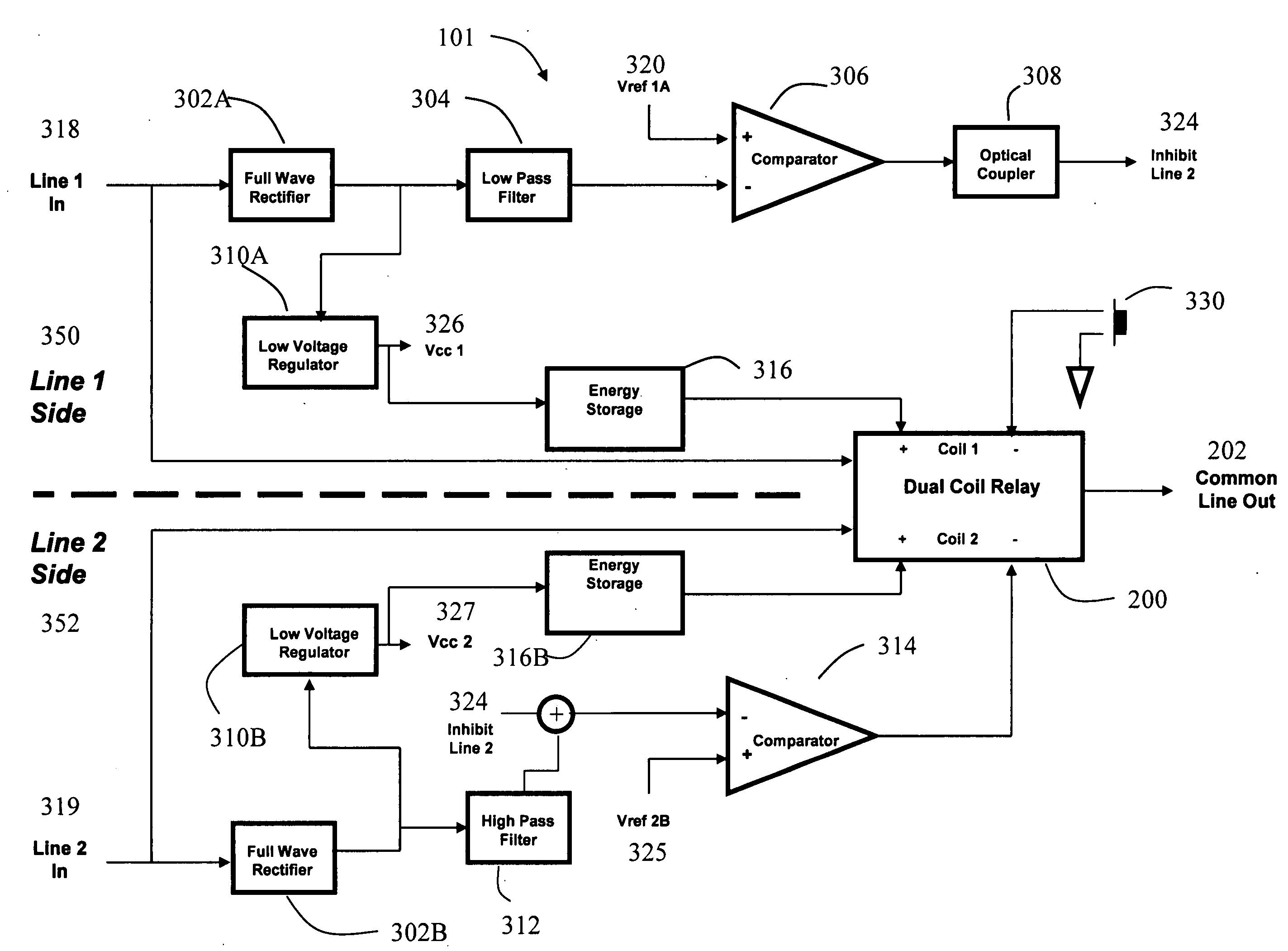
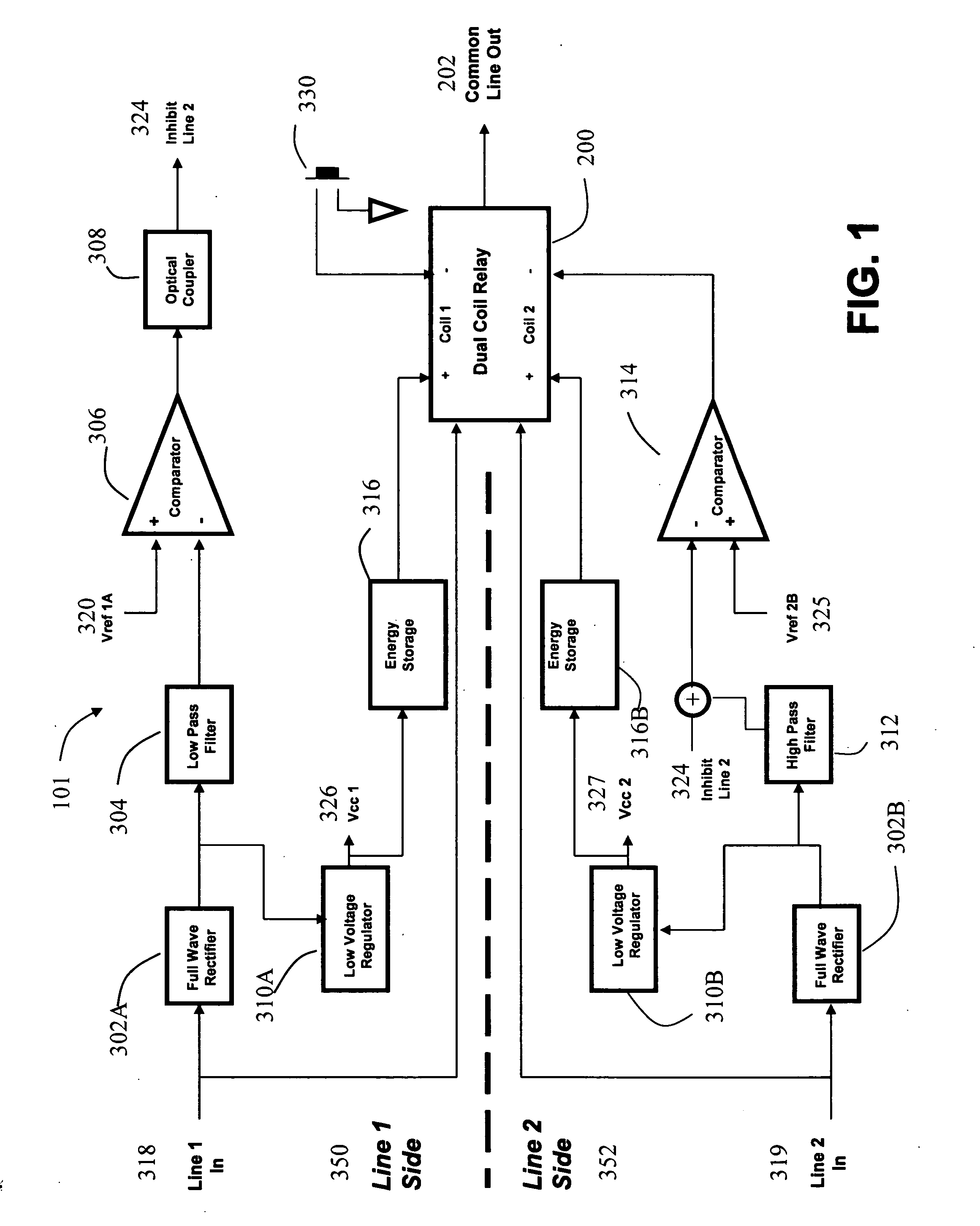
[0028]Referring to FIG. 1 there is depicted a block diagram of switching device 101 of the present disclosure. The switching device 101 is comprised of a dual coil latching relay 200 for switching between either of 2 incoming telephone lines (providing a first type of service and a second type of service) to a common wire pair, Common Line Out 202. The initial position of the relay 200 is such that relay contact connects Line 1 In 318 to the Common Line Out 202. Note that all of the Line 1 Side 350 circuitry is referenced to a local Line 1 ground while all of the Line 2 Side 352 circuitry is referenced to a t local Line 2 ground.

[0029]The Line 1 In 318 signal is connected to a full wave rectifier 302A, wherein the rectifier-302A provides a local ground referenced positive voltage output. The output of the rectifier is coupled to the Low Voltage Regulator 310A and the Low Pass Filter 304. The Low Voltage Regulator 310A provides a nominal 5 VDC power supply, referred to as Vcc1326. Vc...

embodiment 2

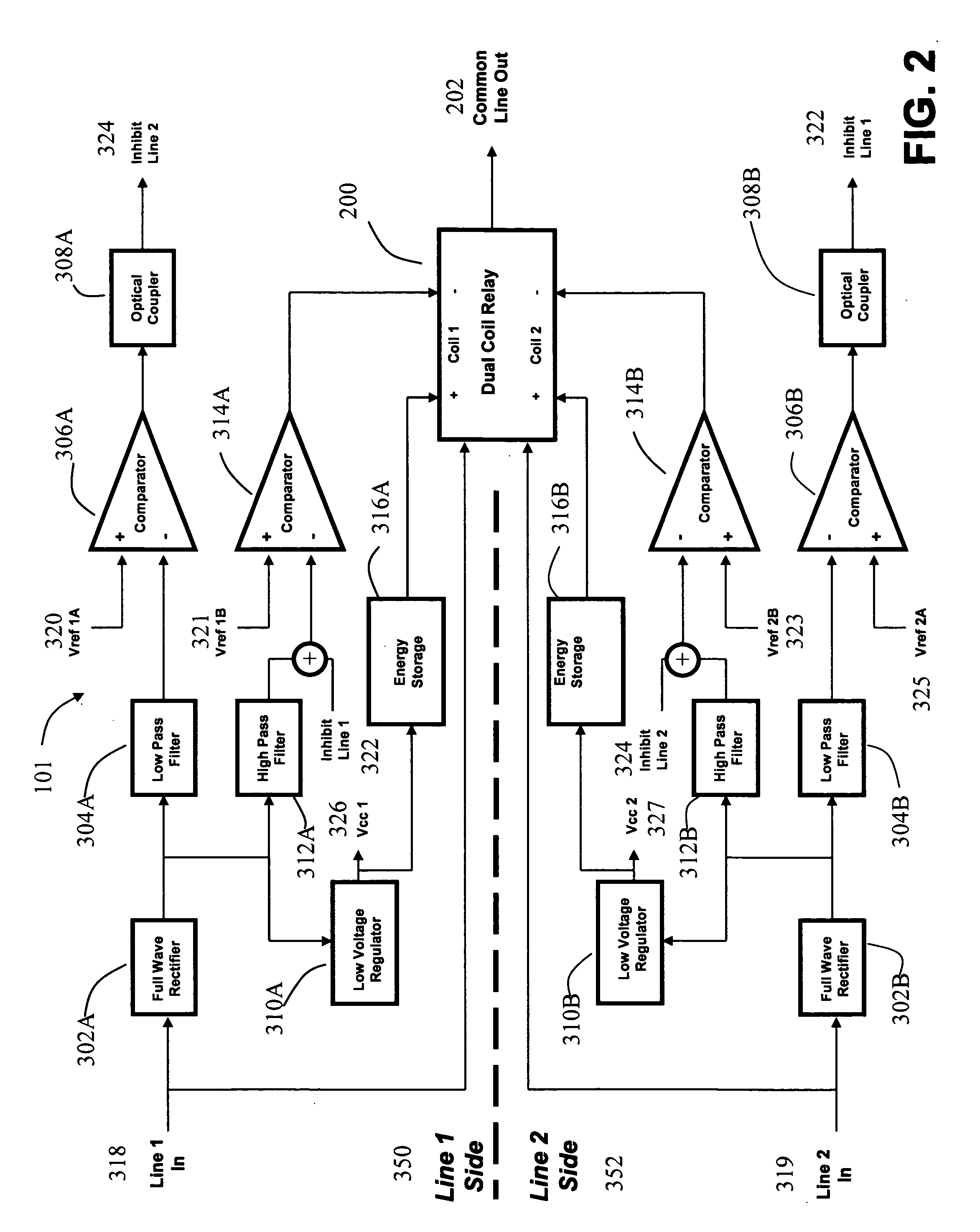
[0040]Referring to FIG. 3 the “primary line” and “secondary line” described above are shown as Line 1 In 318 and Line 2 In 319 respectively. A dual coil latching relay 200 is used to switch the Common Line Out 202 between Line 1 In 318 and Line 2 In 319. The Full Wave Rectifier 302, Low Voltage Regulator 310, Low-Pass Filter 304, High-Pass Filter 312, and Energy Storage 316 blocks perform the identical function that they did in Embodiment 2 so they are not described again here. In this case the Energy Storage Device 316 powers both coils of Relay 200. Note that the Line 1 Side 350 is electrically isolated from the Line 2 side 352 by the Optical Couplers 308 and the Relay 200.

third embodiment

[0041]A Micro-Controller 362 functions as a controller for the third embodiment and drives the 2 coils of the relay 200. The Low-Pass Filters 304 provide signals to the Micro-Controller 362 indicating the hook status of Line 1 In 318 and Line 2 In 319. The High-Pass Filters 312 provide signals to the Micro-Controller 362 indicating if ringing is present on either Line 1 In 318 or Line 2 In 319. The Loop Hold 354 circuit is used to simulate an off-hook condition on Line 1 In 318 when activated by the Micro-Controller 362. Approximately 20 mA of current will flow through the Loop Hold 354 when activated. A Hybrid 356 circuit is used to couple AC signals to and from Line 1 In 318 and the Micro-Controller 362. The Hybrid 356 circuit is constructed from resistors and capacitors although other embodiments are possible. Signals that are sent from the Micro-Controller 362 are passed through the Filter / Driver circuit 358 and coupled to Line 1 In 318 by the Hybrid 356. The Filter / Driver 358 p...


PUM


Abstract

An automatic switching device that alternatively connects the customer's telephony devices via the in-home UTP wiring to the desired telephony service, primary or secondary, upon receiving an incoming call via that service is described. The new device will work reliably with any type of ringing signal provided by the telco, MSO, OTTP, or other service provider. The new device can switch over the entire in-home UTP wiring so that all customer premise equipment connected to the in-home wiring are connected to the desired telephony service no matter the location of the NID, EMTA, PC, ATA or whatever equipment that is providing the service. Furthermore, the new device can either simultaneously disconnect the alternate unused service from the entire in-home wiring or facilitate the use of both services at the same time by implementing call hold feature.

Description

CROSS-REFERENCE TO RELATED APPLICATIONS[0001]This application is related to and claims priority to U.S. Provisional Patent Application No. 60 / 784,159, entitled “Method and Apparatus for Alternatively Switching Between Phone Service Lines” filed Mar. 21, 2006, which is incorporated by reference herein.FIELD OF THE INVENTION[0002]The present disclosure generally relates to telecommunications equipment. More specifically, the disclosure pertains to devices for switching different types of services to a common wire pair at a customer premise.RELATED ART[0003]In telecommunications networks, the subscriber receives a drop line in the form of an unshielded twisted pair (UTP) from the telephone network to a network interface device (NID) on the side of the premise. A wire pair from the NID connects to the customer premise equipment inside the house or business. This type of telephone service delivery has been the preferred method of the Regional Bell operating companies (RBOCs) or independe...

Claims


Application Information

Patent Timeline
Patent Type & Authority Applications(United States)
IPC IPC(8): H04M3/42
CPCH04M1/723H04M7/0069H04M1/733H04M1/715
Inventor BOWERS, MARK T.WILLIAMS, DON PATRICK
Owner BOWERS MARK T
Why Eureka
Try Eureka