
System and method for defining a controlled device command set

a command set and command technology, applied in the field of system and method for defining a controlled device command set, can solve the problems of inability to control, unknown appliances, tedious initial teaching process, etc., and achieve the effect of reducing expenses and little or no extra hardware costs

Active Publication Date: 2007-09-27
UNIVERSAL ELECTRONICS INC
View PDF27 Cites 102 Cited by
  • Summary
  • Abstract
  • Description
  • Claims
  • Application Information

AI Technical Summary

Benefits of technology

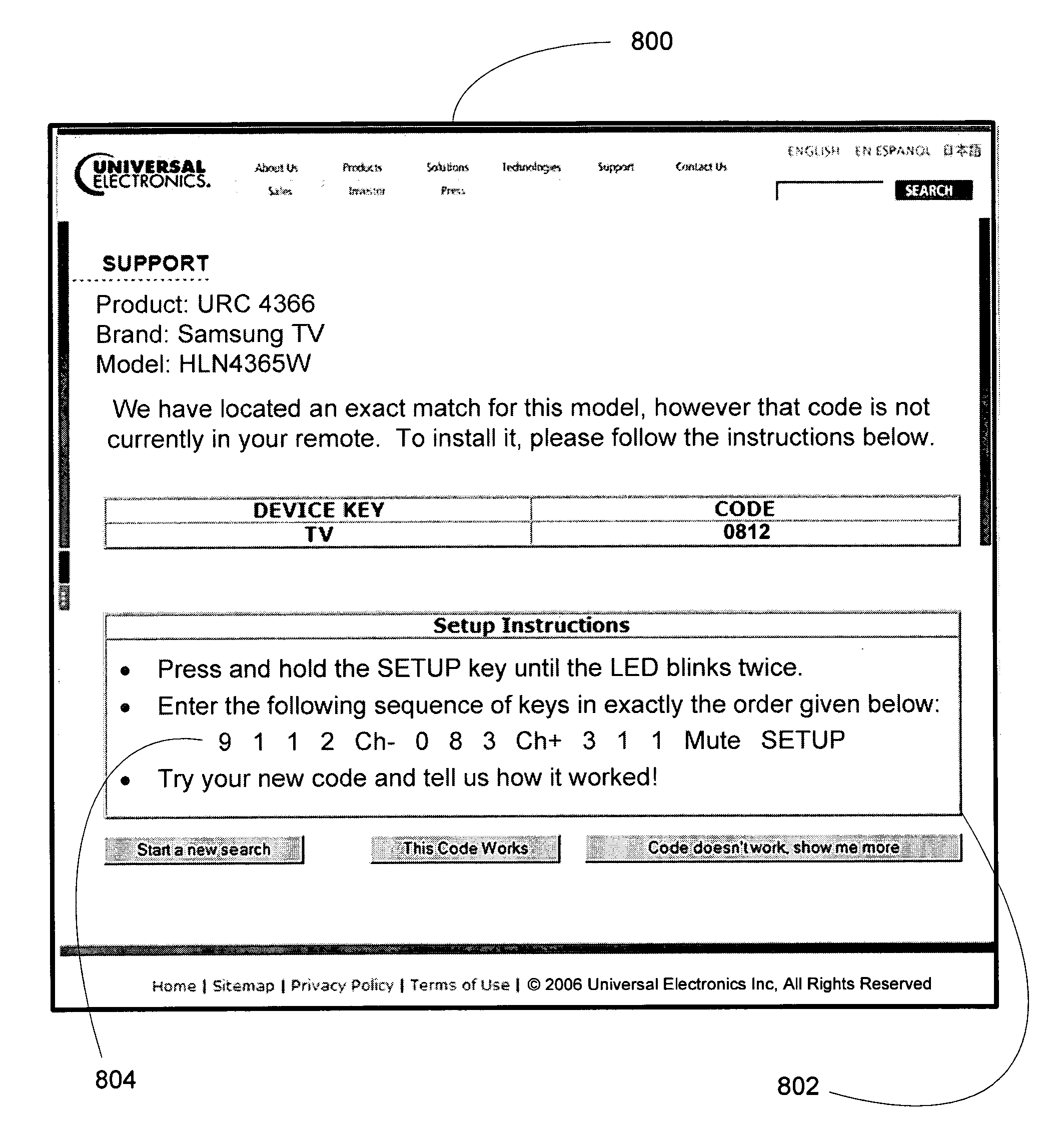
[0003] This invention relates generally to a system and method to enable a controlling device to support the addition of a new command code set definition at little or no extra hardware cost. The method contemplates manual entry by a consumer of a relatively short sequence of keystrokes on the keypad of the controlling device which, as will be seen, may serve to define a new set of appliance command codes which were not previously available in the stored library of codes within the controlling device. While manual entry of the data is preferred as a means to reduce the expenses that are associated with providing a controlling device with data receiving hardware, it will be appreciated that the teachings set forth hereinafter may nevertheless be used to determine data that serves to define a new set of appliance command codes which data may be provided to a controlling device in an automatic or semi-automatic manner without limitation.

Problems solved by technology

However, the required initial teaching process proved tedious and error prone, and universal controlling devices which included preprogrammed libraries of command codes, such as those described in U.S. Pat. No. 4,774,511 or 4,959,810, were introduced to overcome this problem.
These universal controlling devices, however, suffer from the potential drawback that an appliance which is “unknown,” i.e., not already present in the preprogrammed library of codes embedded in the device, cannot be controlled.
All of these approaches, however, increase expense and / or complexity by requiring the provision of additional hardware either internal to the controlling device (e.g., a built-in modem, an IR receiver, etc.) or externally in the form of cables, adapters, etc., or both.

Method used


Image

  • System and method for defining a controlled device command set
  • System and method for defining a controlled device command set
  • System and method for defining a controlled device command set

Examples


Embodiment Construction

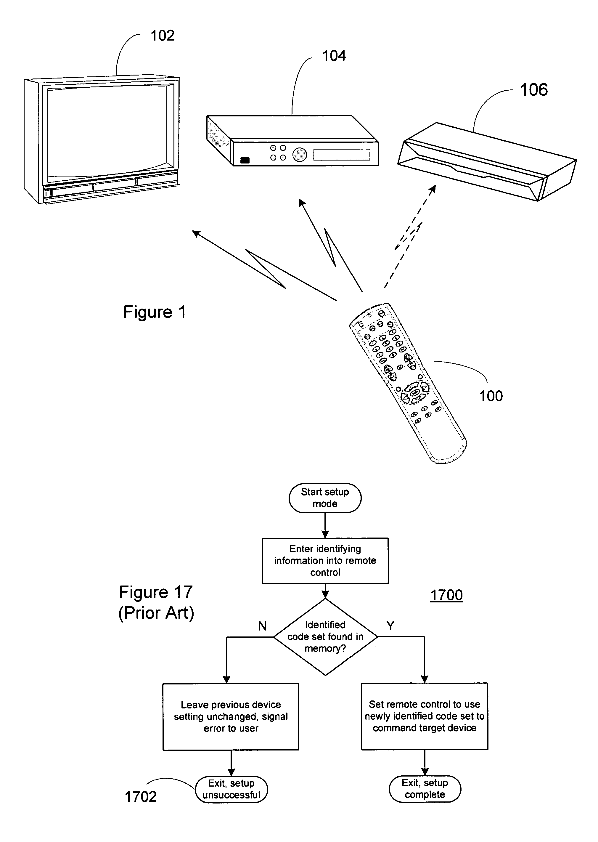
[0024] Turning now to FIG. 1, there is illustrated an exemplary system in which a controlling device 100 has been previously adapted to control various controllable appliances, such as a television 102 and set top box (“STB”) 104, for example by being setup using the methods disclosed in U.S. Pat. No. 4,959,810 or other methods as are well known in the art, all as generally illustrated by the flowchart of FIG. 17. In keeping with the descriptions which follow and as generally illustrated in FIG. 5B, controlling device 100 is now to be further adapted to control a newly-introduced appliance 106, e.g., an appliance introduced at a time after the controlling device 100 left the factory, for which appliance 106 the controlling device 100 was not preprogrammed with a corresponding command code set. As is known in the art, the controlling device 100 is capable of transmitting commands to the appliances, using any convenient IR, RF, Point-to-Point, or networked protocol, to cause the appli...


PUM


Abstract

A system and method for configuring a controlling device to allow the controlling device to generate commands for commanding operations of a new appliance which new appliance was previously unable to be supported by the controlling device. The system and method uses a definition input into the controlling device to create a new device data set for use in generating commands to command operations of the new appliance. The new device data set is a new combination of elements selected from device data sets already stored within a memory of the controlling device.

Description

BACKGROUND [0001] Universal controlling devices, that is, for example, remote controls which are adaptable to issue commands to a multiplicity of appliances of different type and / or manufacture, and the features and functionality provided by such controlling devices are well known in the art. Early universal controlling devices such as, for example, that described in U.S. Pat. No. 4,623,887 were generally “learners,” that is, they were adapted to capture, store, and subsequently play back the command signals of the original equipment remote controls corresponding to the appliances to be controlled. However, the required initial teaching process proved tedious and error prone, and universal controlling devices which included preprogrammed libraries of command codes, such as those described in U.S. Pat. No. 4,774,511 or 4,959,810, were introduced to overcome this problem. These universal controlling devices, however, suffer from the potential drawback that an appliance which is “unkno...

Claims


Application Information

Patent Timeline
IPC IPC(8): G05B11/01
CPCG08C17/00G08C2201/92G08C2201/21
Inventor HUANG, STEVE LANPINGCONWAY, JAMES N. JR.HAYES, PATRICK H.BLACK, JEREMY K.
Owner UNIVERSAL ELECTRONICS INC
Learn More