Device for producing excited and/or ionized particles in a plasma

Inactive Publication Date: 2007-10-04
R3T RAPID REACTIVE RADICALS TECH
View PDF4 Cites 2 Cited by
  • Summary
  • Abstract
  • Description
  • Claims
  • Application Information

AI Technical Summary

Problems solved by technology

However, because of the high production costs for single workpieces or single wafers, it is necessary in the semiconductor industry for economic reasons to produce devices for generating plasma which also achieve good results in expanded reaction chambers.
This method does provide outstanding processing results, but is very time-consuming and thus very costly, since only single wafers may be processed simultaneously.
The problem is that the currently known devices which achieve good processing results are only suitable for single or a few workpieces or wafers.
Devices for multiple workpieces (such as laser mirrors), sensors, or silicon wafers currently do not provide adequate processing results or may not be used in excitation chambers for high temperatures.
According to the prior art, devices are currently available, as disclosed, for example, in DE-A1-19847848, which may only be attached externally to the reaction chambers because of their construction, but are only suitable for small reaction chambers because of the limited range of the excited particles.
Known devices for larger reaction chambers either cannot generate a plasma of appropriate density to achieve good results, or are not capable of resisting the high temperatures in the excitation chamber.
The disadvantages of the currently available devices are in the limited dimensions of high-density plasma zones, the inadequate uniformity of the plasma zones, and the low temperature resistance of the apparatus.

Method used


Image

  • Device for producing excited and/or ionized particles in a plasma
  • Device for producing excited and/or ionized particles in a plasma
  • Device for producing excited and/or ionized particles in a plasma

Examples


first embodiment

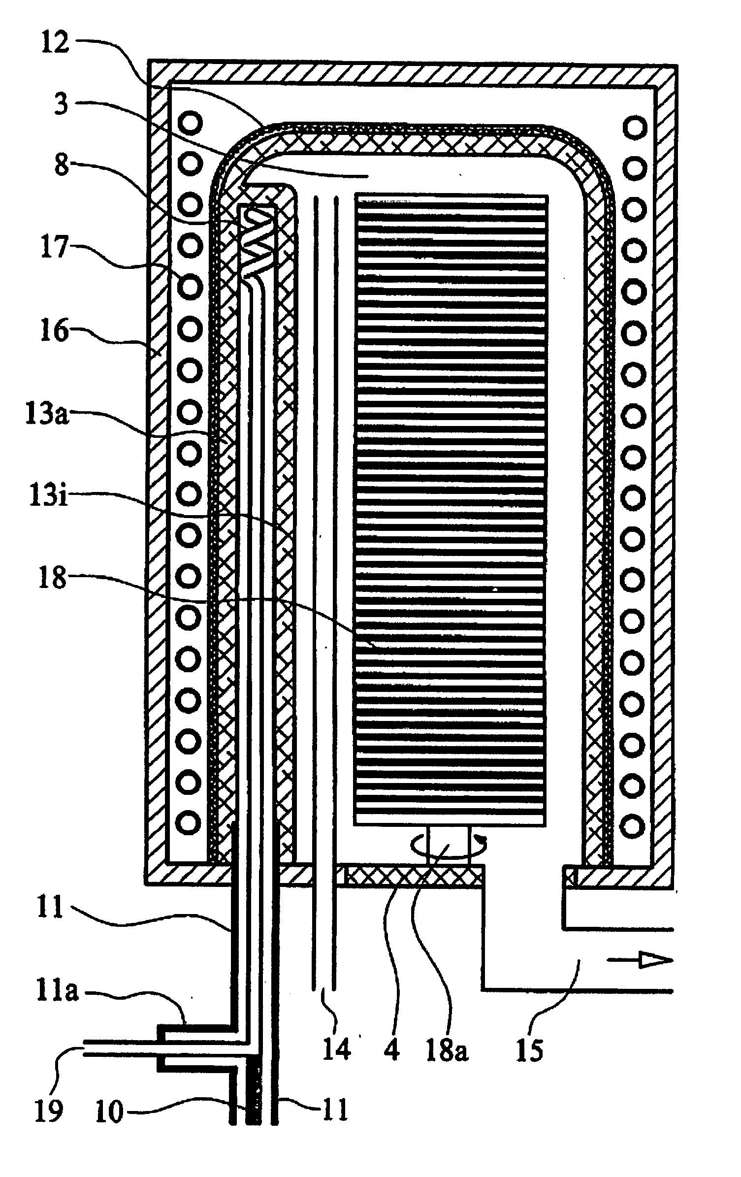
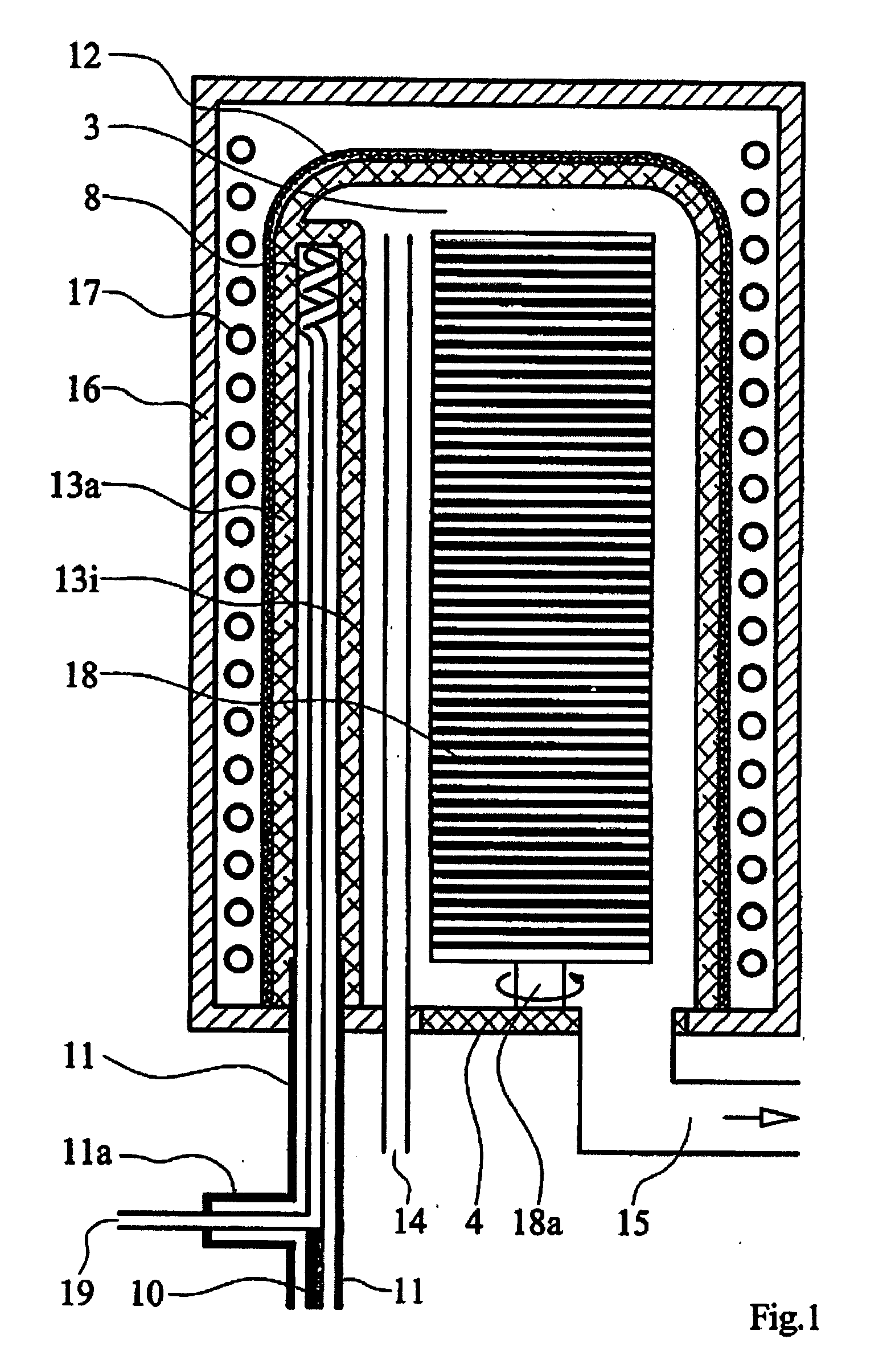
[0040]FIG. 1 shows a schematic illustration of the device according to the present invention. An excitation chamber and / or a cylindrically implemented inner chamber is identified by 3, in which workpieces 18, such as silicon wafers which are used for mass production of electronic components, may be subjected to a plasma treatment. Furthermore, a tubular gas inlet 14 projects into the inner chamber, through which process gas may be introduced into the inner chamber 3. The end of the gas inlet is situated well into the inner chamber, so that the process gas is well mixed. A U-profile implementation (not shown) of the gas inlet 14 in the inner chamber 3 is also advantageous, the opening of the U-profile being directed toward the insulator 13i of the internal conductor. A gap is thus formed between the legs of the U-shaped gas inlet 14 and the insulator 13i of the internal conductor. With such a gas inlet, the process gas must pass the area having the greatest plasma density in proximit...

third embodiment

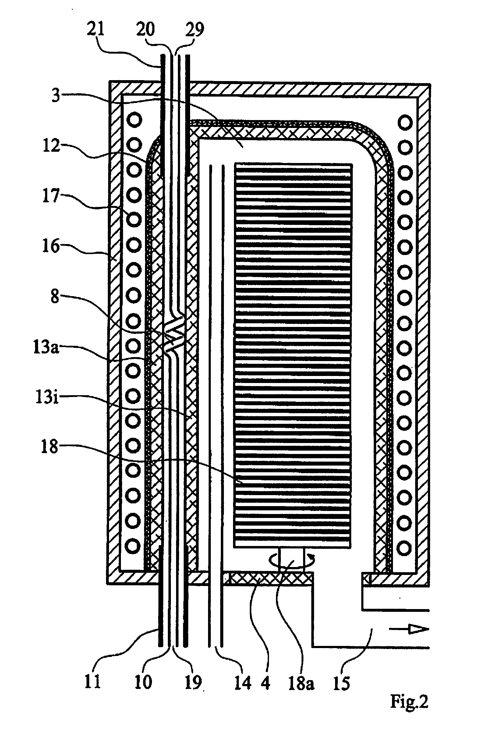
[0047] see FIG. 3, the coaxial internal conductor 10 is implemented as U-shaped and as coiled on one of its U-legs in its longitudinal direction in the middle area. The inlet area 19 of the coaxial internal conductor 10 and the outlet area 39 of the coaxial internal conductor 30 are thus situated neighboring one another and both end outside the inner chamber 3. The other U-leg is not implemented as coiled in its longitudinal direction in the middle area, but rather is implemented as linear from its inlet area along its entire length. Along this length, the coaxial external conductor 11 runs coaxially to the coaxial internal conductor 10, so that the transport of the electromagnetic wave up to the upper end of the excitation chamber 3 is made possible, which corresponds to an energy feed supplied from above as shown in FIG. 2. An additional coaxial external conductor 31 is situated neighboring the coaxial external conductor 11 in such a way that it runs coaxially to the coaxial inte...


PUM

PropertyMeasurementUnit
Widthaaaaaaaaaa
Areaaaaaaaaaaa
aaaaaaaaaa

Abstract

A device for generating excited and / or ionized particles in a plasma made of a process gas, having an inner chamber, which is implemented as cylindrical and in which a plasma zone may be generated, a coaxial internal conductor, a coaxial external conductor, an inlet, using which process gas may be supplied into the inner chamber, and an outlet using which process gas may be discharged from the inner chamber, wherein the coaxial internal conductor at least partially has a curved shape.

Description

CROSS-REFERENCE TO RELATED APPLICATIONS [0001] This application claims priority of German Patent Application DE102004039468.7 filed Aug. 14, 2004, the entire disclosure of which is incorporated herein by reference. FIELD OF THE INVENTION [0002] The present invention relates to a device for generating excited and / or ionized particles in a plasma. BACKGROUND OF THE INVENTION [0003] According to the prior art, it is known that good results are achieved for single workpieces or single wafers using devices for generating plasma, as described in DE-A1-19847848. However, because of the high production costs for single workpieces or single wafers, it is necessary in the semiconductor industry for economic reasons to produce devices for generating plasma which also achieve good results in expanded reaction chambers. Thus, for example, in recent years, due to the introduction of new materials, structures of the individual elements on the components which are becoming smaller and smaller, and ...

Claims


Application Information

Patent Timeline
IPC IPC(8): C23C16/00
CPCH01J37/3222H01J37/32724H01J37/32541
Inventor GSCHWANDTNER, ALEXANDER
Owner R3T RAPID REACTIVE RADICALS TECH
Why Eureka
Try Eureka