
Internal combustion engine and transporation apparatus incorporating the same

a technology of internal combustion engine and transporation apparatus, which is applied in the direction of machines/engines, mechanical equipment, cylinders, etc., can solve the problems of reducing dimensional precision, affecting the motion of the piston, and cylinder liner 620/b> not being fitted with a high precision, etc., to prevent electrolytic corrosion, high precision, and prevent electrolytic corrosion

Inactive Publication Date: 2007-10-04
YAMAHA MOTOR CO LTD
View PDF8 Cites 17 Cited by
  • Summary
  • Abstract
  • Description
  • Claims
  • Application Information

AI Technical Summary

Benefits of technology

The present invention provides an internal combustion engine with a wet liner that prevents electrolytic corrosion and a transportation apparatus that includes this engine. The engine has a cylinder block and a cylinder liner that are fitted together with high precision, using a sealing member to prevent leakage of coolant. The cylinder block and cylinder liner have positioning surfaces that determine their relative position, and the sealing member is located between these surfaces and the water jacket. The positioning surfaces are not required to have high precision, and the cylinder liner is coated to prevent electrolytic corrosion. The cylinder block and cylinder liner are spaced apart from each other, preventing peeling of the coating during operation and press-fitting of the cylinder liner. The invention suppresses electrolytic corrosion for long periods of time and provides a high-precision engine with a wet liner.

Problems solved by technology

However, painting would induce a decrease in dimensional precision, such that the cylinder block 610 and the cylinder liner 620 might not be fitted together with a high precision.
If the fitting precision between the cylinder block 610 and the cylinder liner 620 is lowered, the sliding motion of the piston may be hindered, and it may become impossible to maintain airtightness or sealing ability.

Method used


Image

  • Internal combustion engine and transporation apparatus incorporating the same
  • Internal combustion engine and transporation apparatus incorporating the same
  • Internal combustion engine and transporation apparatus incorporating the same

Examples


Embodiment Construction

[0045]Hereinafter, preferred embodiments of the present invention will be described with reference to the accompanying drawings. Note that the present invention is not to be limited to the following preferred embodiments.

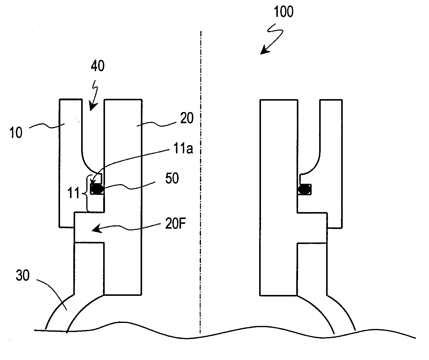
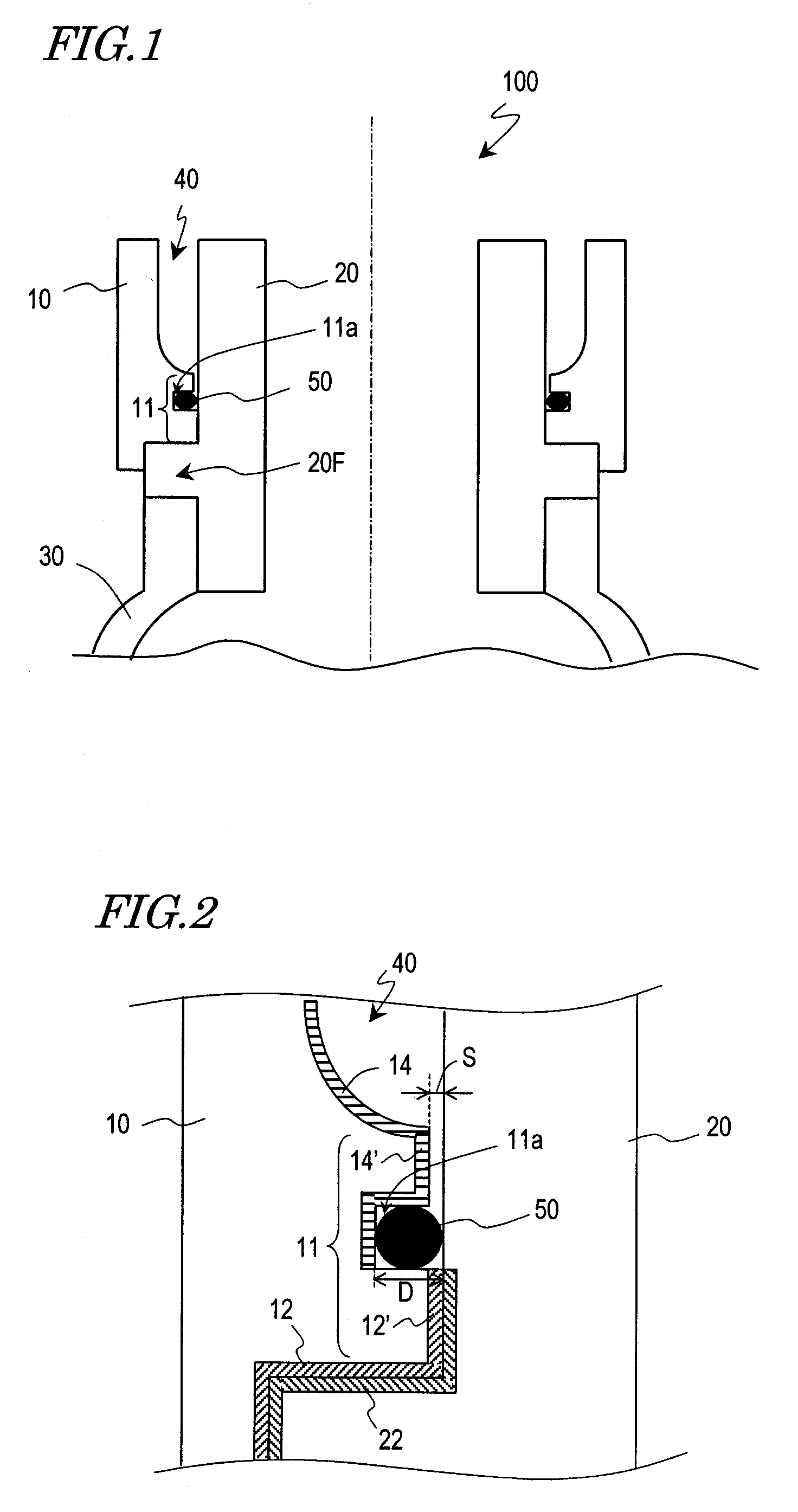
[0046]FIG. 1 schematically shows the cross-sectional structure of an internal combustion engine 100 according to the present preferred embodiment. In FIG. 1, only some of the component elements of the internal combustion engine 100 are illustrated for ease of description.

[0047]The internal combustion engine 100 preferably includes a cylinder block 10; a cylinder liner (also referred to as a cylinder sleeve) 20 which is fitted onto the cylinder block 10; and a crankcase 30 accommodating a crankshaft (not shown).

[0048]The cylinder block 10 and the cylinder liner 20 according to the present preferred embodiment are each preferably formed as a separate piece from the crankcase 30. A brim-like flange portion 20F is provided in the cylinder liner 20, the flange portion 20...


PUM


Abstract

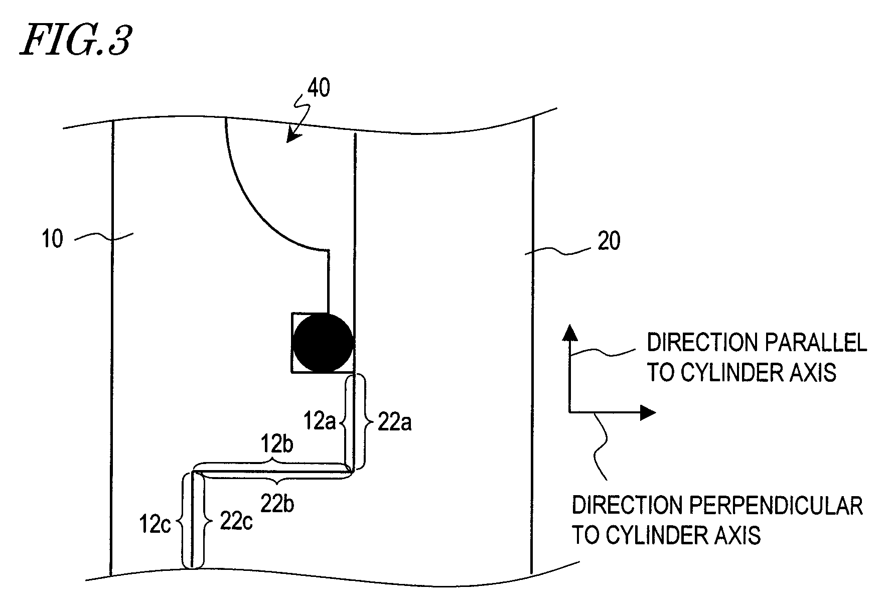
An internal combustion engine includes a cylinder block formed of a metal material, a cylinder liner formed of a metal material different from that of the cylinder block, the cylinder liner being fitted onto the cylinder block, a water jacket provided between the cylinder block and the cylinder liner for retaining a coolant, and a sealing member provided in contact with the cylinder block and the cylinder liner, the sealing member preventing leakage of the coolant from the water jacket. The cylinder block and the cylinder liner have respective positioning surfaces, each of which determines a relative position against the other. The positioning surfaces are provided on the opposite side of the sealing member from the water jacket. The cylinder block and the cylinder liner are spaced apart from each other, in between the sealing member and the water jacket.

Description

BACKGROUND OF THE INVENTION[0001]1. Field of the Invention[0002]The present invention relates to an internal combustion engine, and in particular, to a water-cooling type internal combustion engine in which a cylinder block and a cylinder liner are formed of different metal materials. Moreover, the present invention relates also to a transportation apparatus incorporating such an internal combustion engine.[0003]2. Description of the Related Art[0004]Currently, internal combustion engines are used as motive power sources for various transportation apparatuses. In the interior of a cylinder block, which is a fundamental part of an internal combustion engine, a piston moves up and down (reciprocates) very rapidly. Therefore, the cylinder block is required to have a high abrasion resistance. Accordingly, in order to improve the abrasion resistance of the cylinder block, it is common practice to fit a cylinder liner onto a cylinder block.[0005]FIG. 12 shows an example of cylinder block ...

Claims


Application Information

Patent Timeline
Patent Type & Authority Applications(United States)
IPC IPC(8): F02F1/10F02F1/00
CPCF02F1/16
Inventor HIRAMITSU, YASUHIROKOIKE, TOSHIKATSUINAMI, JUNICHI
Owner YAMAHA MOTOR CO LTD
Learn More