Fuel injector

Inactive Publication Date: 2007-10-04
AISAN IND CO LTD
View PDF3 Cites 16 Cited by
  • Summary
  • Abstract
  • Description
  • Claims
  • Application Information

AI Technical Summary

Benefits of technology

[0006] Accordingly, it is an object of the present invention to provide an effective technique for improvi

Problems solved by technology

However, the valve seat formed of a material having a smaller Young's modulus has

Method used


Image

  • Fuel injector
  • Fuel injector
  • Fuel injector

Examples


Embodiment Construction

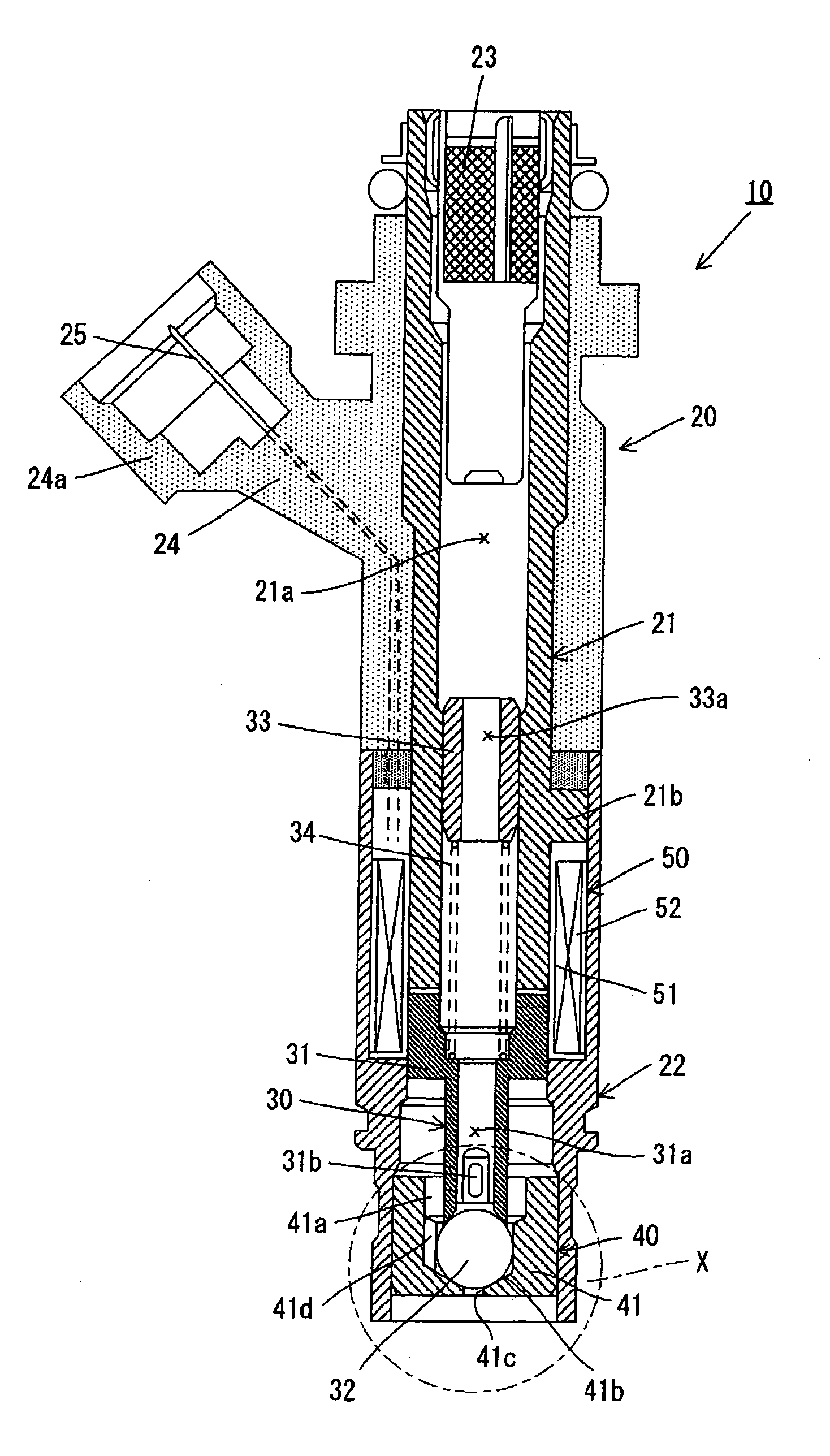
[0019] The present invention is applied as a fluid control valve for controlling fluid such as liquid and gas. Suitably, the present invention is applied as a fuel injector for controlling the flow rate of fuel, including liquid fuel such as gasoline, liquefied petroleum gas (LPG) and liquefied natural gas (LNG) and gaseous fuel such as hydrogen.

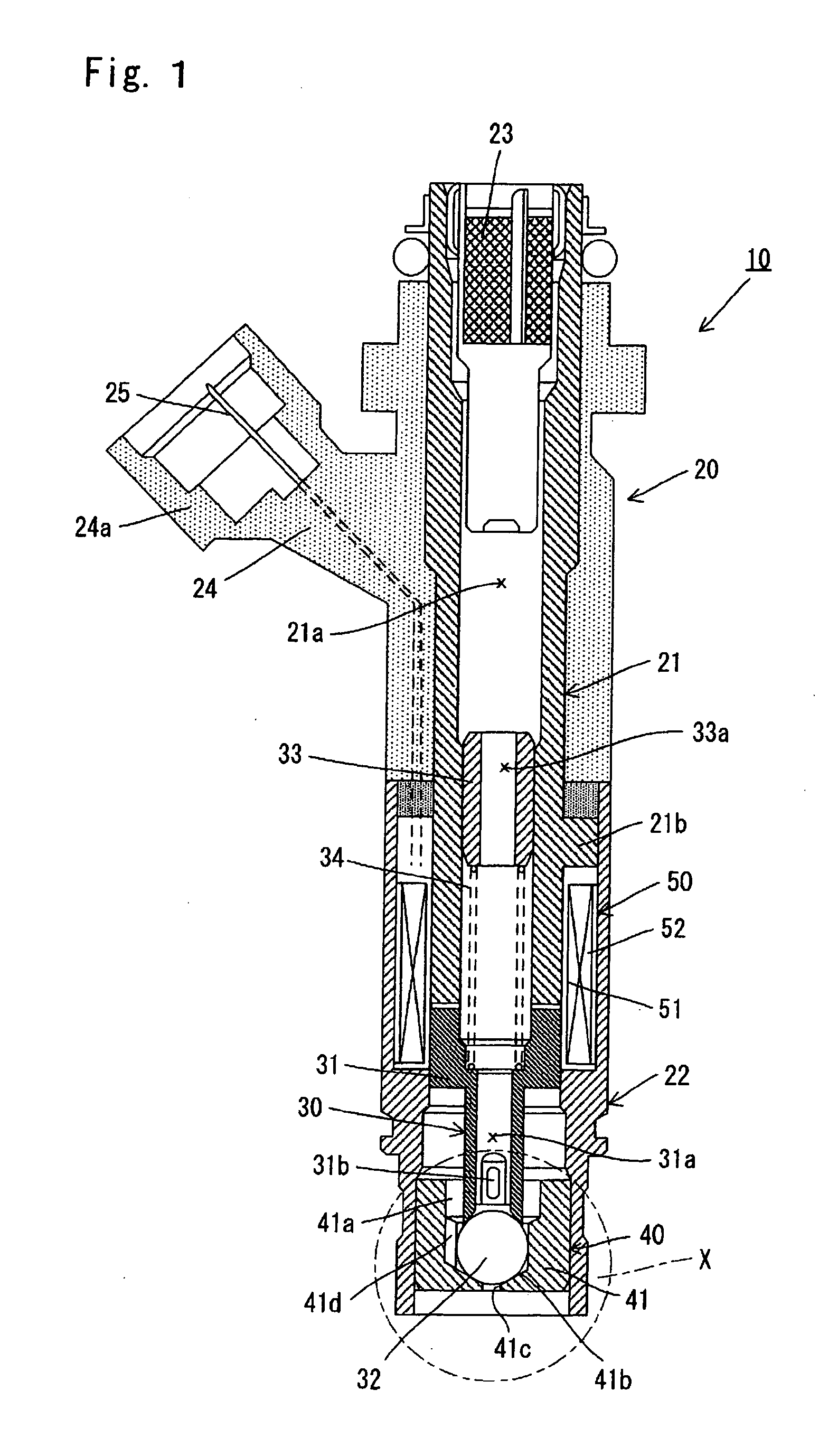
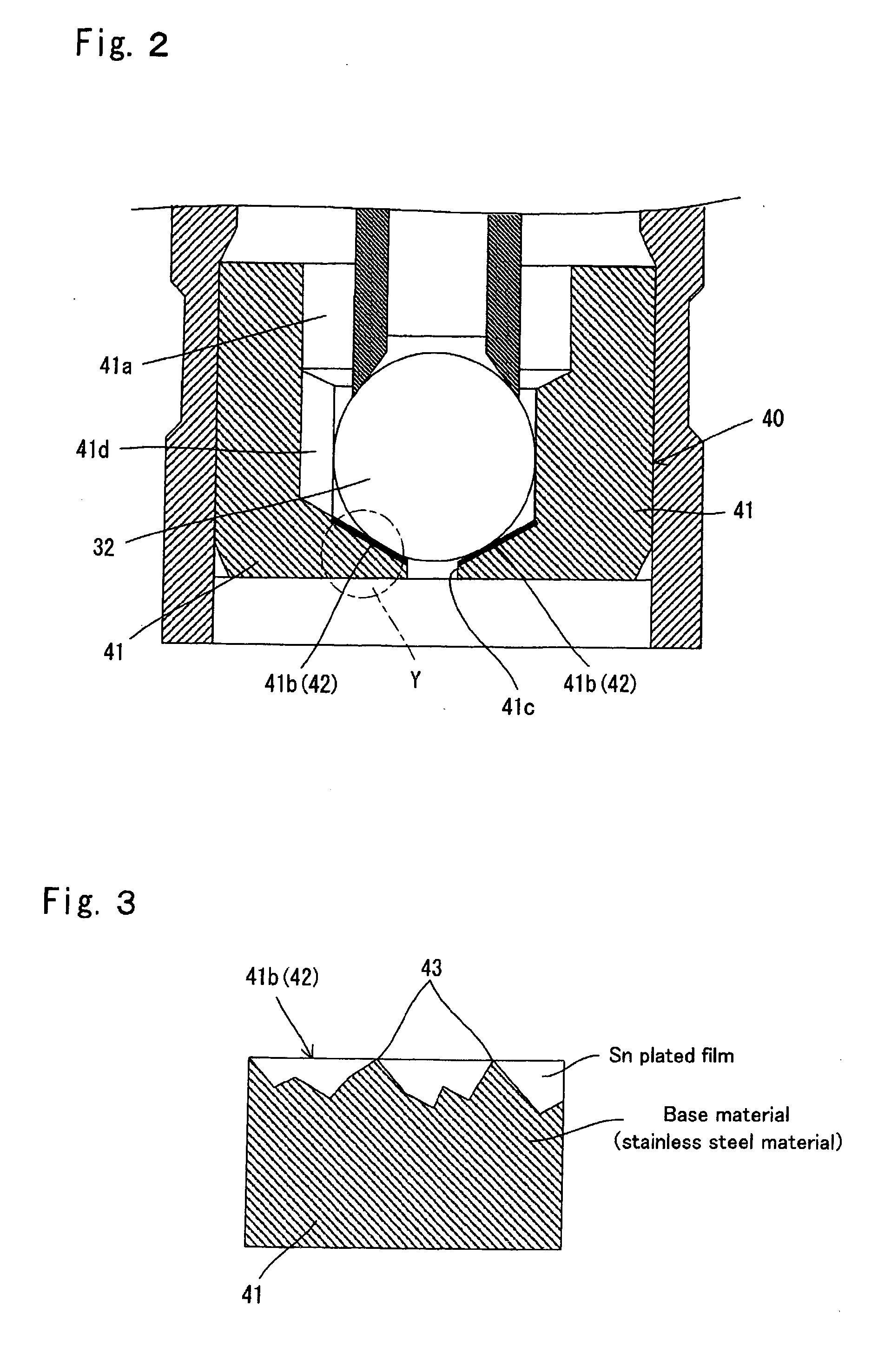
[0020] The fuel injector and the fluid control valve (hereinafter generically referred to as “fuel injector”) include a valve seat having a fuel jet opening (fluid outlet opening), and a valve which contacts and separates from the valve seat. The surface of a valve side contact portion or a valve seat side contact portion which contact each other typically has protrusions and depressions of the base material. The sealing performance of the fuel injector may be deteriorated due to the existence of depressions.

[0021] In a fuel injector according to a representative embodiment of the present invention, a base material and a film softer than t...


PUM


Abstract

The invention provides an effective technique for improving the sealing performance and durability of a fluid control valve, particularly a fuel injector. The fuel injector 10 has a ball valve 32 and a valve seat body 41. A fuel jet opening 41c formed in the valve seat body 41 is closed when the ball valve 32 contacts a sealing surface 41b of the valve seat body 41, while being opened when the ball valve 31 separates from the sealing surface 41b of the valve seat body 41. A stainless steel base material and a Sn plated film softer than the base material form a smooth surface 42 on the sealing surface 41b of the valve seat body 41.

Description

BACKGROUND OF THE INVENTION [0001] 1. Field of the Invention [0002] The present invention relates to a fluid control valve for controlling the flow rate of fluid, and more particularly to a fuel injector for controlling the injection rate of fuel. [0003] 2. Description of the Related Art [0004] A fuel injector used for an internal combustion engine includes a valve and a valve seat having a fuel jet opening. The fuel injector is placed in a closed state in which the valve is in contact with the valve seat so that the fuel jet opening is closed, or in an open state in which the valve is not in contact with the valve seat so that the fuel jet opening is open. In such a fuel injector, the sealing performance for sealing in fuel between the valve and the valve seat is desired to be improved. Japanese non-examined laid-open patent publication No. 2003-65189 discloses a fluid control valve provided with a valve seat having a smaller Young's modulus than the valve. In this known fluid cont...

Claims


Application Information

Patent Timeline
IPC IPC(8): F02M47/02F02M63/00F02M51/00
CPCF02M61/166F02M61/168F02M61/18F02M2200/9061F02M61/188F02M2200/02F02M2200/9038F02M61/1866
Inventor KATO, KOJISUGIYAMA, FUMIYASUNISHIBU, HIDEAKIKAWAZOE, HIROSHI
Owner AISAN IND CO LTD
Why Eureka
Try Eureka