Braking apparatus for vehicle

a technology for braking apparatus and vehicles, which is applied in the direction of braking systems, braking components, transportation and packaging, etc., can solve the problems of insufficient regenerative braking force in the total braking force required, the driver may have an uncomfortable feeling that the brake pedal is further depressed or lowered without his or her further action, and the driver of the vehicle may have an uncomfortable feeling that the brake pedal is depressed

Active Publication Date: 2007-10-04
ADVICS CO LTD
View PDF11 Cites 61 Cited by
  • Summary
  • Abstract
  • Description
  • Claims
  • Application Information

AI Technical Summary

Benefits of technology

[0012]According to an aspect of the present invention, a braking apparatus for a vehicle includes a hydraulic brake apparatus including a master cylinder, a pump, a hydraulic pressure control valve, and a fluid passage and generating a basic hydraulic pressure by the master cylinder in response to a brake operation so as to apply the generated basic hydraulic pressure to wheel cylinders provided at respective wheels connected to the master cylinder by means of the fluid passage at which the hydraulic pressure control valve is provided so that a basic hydraulic braking force is generated at the wheels, the hydraulic brake apparatus generating a controlled hydraulic pressure by driving the pump by a motor so as to apply the generated controlled hydraulic pressure to the wheel cylinders so that a controlled hydraulic braking force is generated at the wheels, a regenerative brake apparatus causing a regenerative braking force to be generated at any of the wheels in response to a state of the brake operation, and braking force replacement controlling means for gradually replacing the regenerative braking force with the controlled hydraulic braking force while braking during which at least the regenerative braking force is applied for a purpose of achieving a braking force replacement control to ensure a total braking force required for the wheels by decreasing the regenerative braking force at a gradient within a predetermined range and by increasing the controlled hydraulic braking force in response to the decrease of the regenerative braking force.

Problems solved by technology

When the vehicle speed decreases, the regenerative braking force decreases accordingly, which may lead to insufficiency of the regenerative braking force in the total braking force required for the wheels.
As a result, the driver may have an uncomfortable feeling that the brake pedal is further depressed or lowered without his or her further action.
Accordingly, the driver of the vehicle may have an uncomfortable feeling that the brake pedal is depressed suddenly without further action.
In addition, in the case of replacing the regenerative braking force with the controlled hydraulic braking force, a brake fluid supplied by the pump at the time of replacement start becomes insufficient and thus a start-up delay of the controlled hydraulic braking force may occur, thereby preventing the deceleration that has been achieved before replacement from being retained.

Method used


Image

  • Braking apparatus for vehicle
  • Braking apparatus for vehicle
  • Braking apparatus for vehicle

Examples


first embodiment

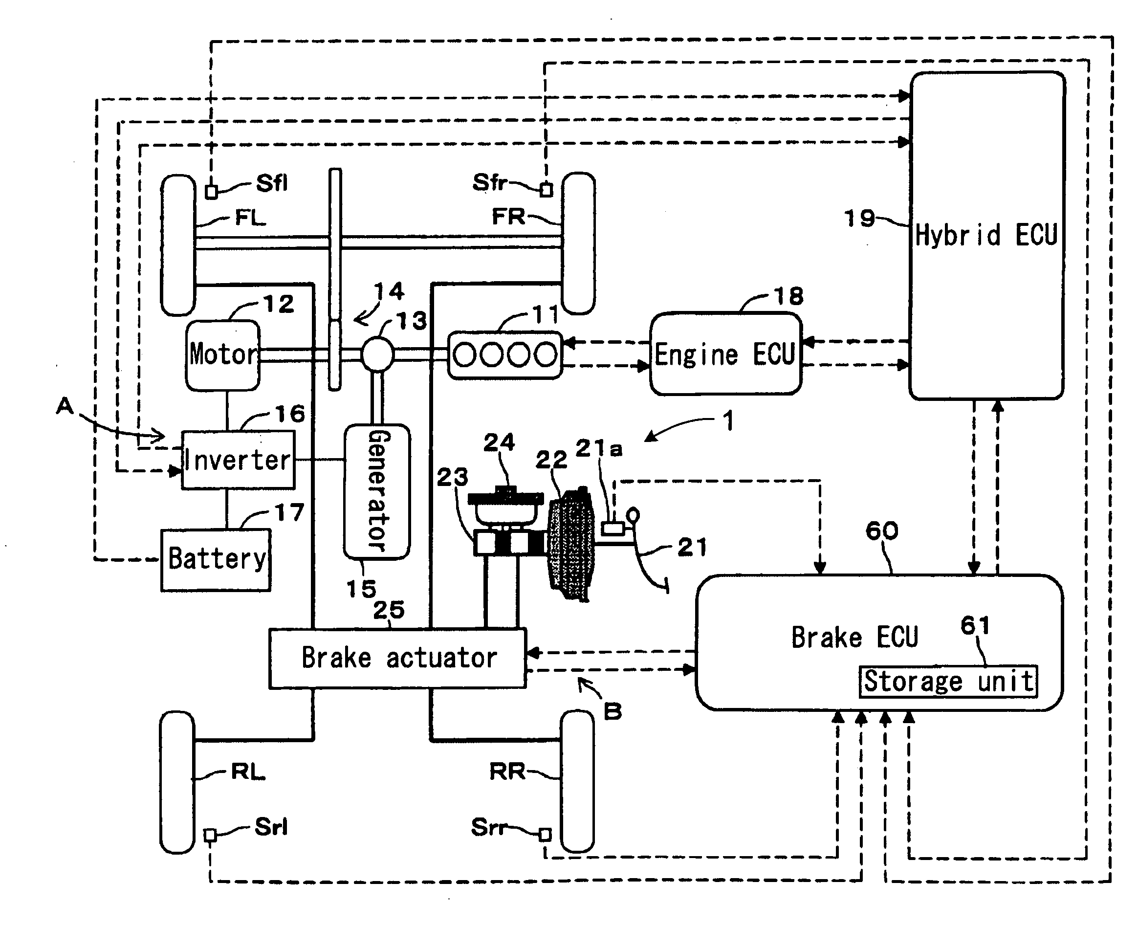
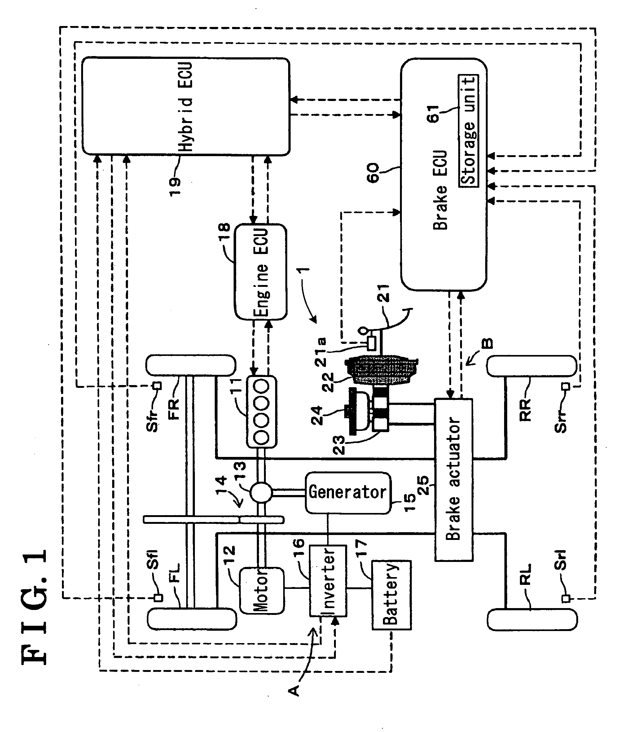
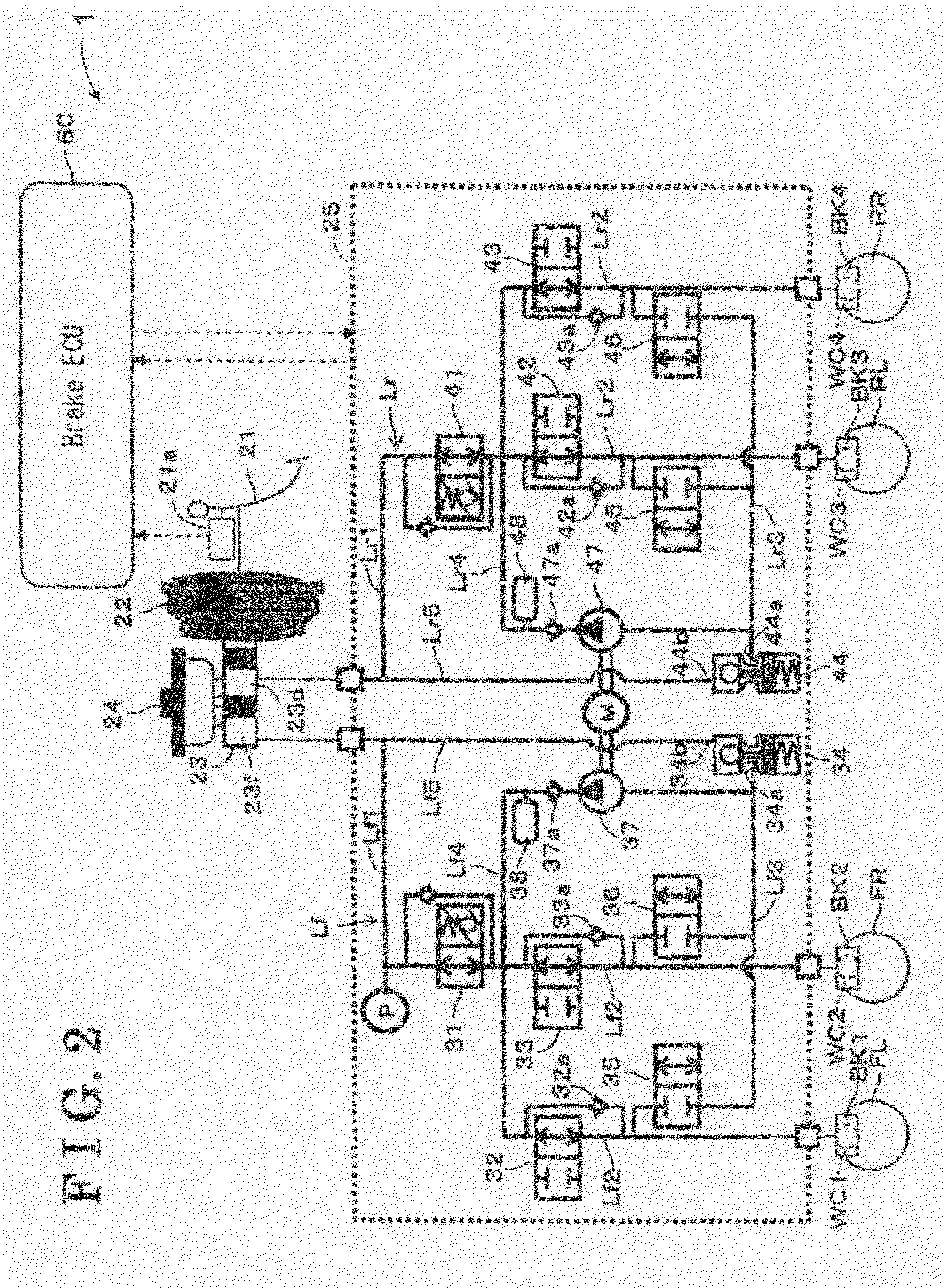
[0044]A braking apparatus for a vehicle 1 according to the present invention employed in a hybrid vehicle will be explained with reference to the attached drawings. FIG. 1 is a schematic view illustrating a structure of the hybrid vehicle. FIG. 2 is a schematic view illustrating a structure of a hydraulic brake apparatus of the hybrid vehicle. In the hybrid vehicle, driving wheels, i.e., front-left and front-right wheels FL and FR, for example, are driven by means of a hybrid system as shown in FIG. 1. The hybrid system is a power train using two types of power sources, i.e., an engine 11 and an electric motor 12, in combination. According to the present embodiment, a parallel hybrid system in which both the engine 11 and the motor 12 directly drive the wheels is used. Besides the parallel hybrid system, a series hybrid system is known, in which an electric motor drives the wheels and an engine serves as an electric power supply source to the motor.

[0045]The hybrid vehicle incorpora...

second embodiment

[0124]As shown in FIG. 12, the hydraulic brake apparatus B has a hysteresis in a correlation between the wheel cylinder pressure and the stroke of the brake pedal 21. That is, on the assumption that the amount of stroke of the brake pedal 21 is same, the wheel cylinder pressure is larger when the brake pedal 21 is depressed as compared to the wheel cylinder pressure generated when the brake pedal 21 is released.

[0125]This is because the vacuum booster 22 includes an atmospheric pressure inlet valve that is opened to move a booster output rod of the vacuum booster 22 in a forward direction when the brake pedal 21 is depressed, and a negative pressure inlet valve that is opened to move the booster output rod in a rearward direction when the brake pedal 21 is released. The opening timings between the atmospheric pressure inlet valve and the negative pressure inlet valve are different from each other and this difference achieves the hysteresis of the stroke. In addition, the master cyl...

third embodiment

[0174]An operation of the braking apparatus for a vehicle 1 will be explained with reference to FIGS. 18 to 25. Before explaining the detailed operation of the braking apparatus 1, a reason why the operation is performed will be described below.

[0175]FIG. 18 is a graph showing a correlation between a wheel cylinder pressure and an amount of stroke of a brake pedal 21. As illustrated in FIG. 18, the wheel cylinder pressure and the amount of stroke are not in a proportional relation. In a range where the stroke amount is small, an increase of the wheel cylinder pressure relative to an increase of the stroke amount is small. On the other hand, in a range where the stroke amount is large, the increase of the wheel cylinder relative to the increase of the stroke amount is large.

[0176]Thus, for example, when the stroke amount is changed from a point A to a point B as illustrated in FIG. 18 in the case of replacing the regenerative braking force with the controlled hydraulic braking force...


PUM


Abstract

A braking apparatus for a vehicle includes a hydraulic brake apparatus generating a basic hydraulic pressure so that a basic hydraulic braking force is generated at wheels, the hydraulic brake apparatus generating a controlled hydraulic pressure so that a controlled hydraulic braking force is generated at the wheels, a regenerative brake apparatus causing a regenerative braking force to be generated at any of the wheels, and braking force replacement controlling means for gradually replacing the regenerative braking force with the controlled hydraulic braking force while braking during which at least the regenerative braking force is applied for a purpose of achieving a braking force replacement control to ensure a total braking force required for the wheels by decreasing the regenerative braking force at a gradient within a predetermined range and by increasing the controlled hydraulic braking force in response to the decrease of the regenerative braking force.

Description

CROSS REFERENCE TO RELATED APPLICATIONS[0001]This application is based on and claims priority under 35 U.S.C. § 119 to Japanese Patent Application No. 2006-102064 filed on Apr. 3, 2007, No. 2006-111242 filed on Apr. 13, 2007, No. 2006-102461 filed on Apr. 3, 2007, and 2006-106191 filed on Apr. 7, 2007, the entire contents of which are incorporated herein by reference.FIELD OF THE INVENTION[0002]This invention generally relates to a braking apparatus for a vehicle. More particularly, this invention pertains to a braking apparatus for a vehicle that achieves a total braking force applied to wheels in response to a brake operation state as a sum of a hydraulic braking force generated by a hydraulic brake apparatus and a regenerative braking force generated by a regenerative brake apparatus.BACKGROUND[0003]A known braking apparatus for a vehicle such as disclosed in JP2006-21745A includes a hydraulic brake apparatus and a regenerative brake apparatus. The hydraulic brake apparatus gener...

Claims


Application Information

Patent Timeline
Patent Type & Authority Applications(United States)
IPC IPC(8): B60T8/64
CPCB60K6/445B60L7/26B60T1/10B60T2270/602Y02T10/6239B60W10/184B60W10/30B60W20/00B60W30/18127B60W10/04Y02T10/62B60L7/10
Inventor MAKI, KAZUYAKOKUBO, KOICHINAITO, MASAYUKI
Owner ADVICS CO LTD
Why Eureka
Try Eureka