
System, method, and article of manufacture for controlling operation of an electrical power generation system

a technology of electrical power generation system and control system, which is applied in the direction of process and machine control, final product manufacturing, instruments, etc., can solve the problems of control system inability to maintain consistent dynamic performance of output voltage or reactive power at the desired level

Active Publication Date: 2007-10-04
GENERAL ELECTRIC CO
View PDF13 Cites 71 Cited by
  • Summary
  • Abstract
  • Description
  • Claims
  • Application Information

AI Technical Summary

Benefits of technology

[0079] The inventive system, method, and article of manufacture for controlling operation of a wind farm provide a substantial advantage over other system and methods. In particular, system, method, and article of manufacture provide a technical effect of generating a desired power command to induce the wind farm to have an output parameter at a point of interconnection between the wind farm and the electrical grid that approaches a desired output parameter value.

Problems solved by technology

However, a well-known problem associated with a conventional control system is that the control system is unable to maintain consistent dynamic performance of output voltage or reactive power at a desired level at the point of interconnection to the electrical grid, due to changing wind turbine conditions and electrical grid conditions such as (i) a variable number of turbines on line, (ii) changes in impedance of the electrical grid, and (iii) a switched capacitor or reactor banks.

Method used


Image

  • System, method, and article of manufacture for controlling operation of an electrical power generation system
  • System, method, and article of manufacture for controlling operation of an electrical power generation system
  • System, method, and article of manufacture for controlling operation of an electrical power generation system

Examples


Embodiment Construction

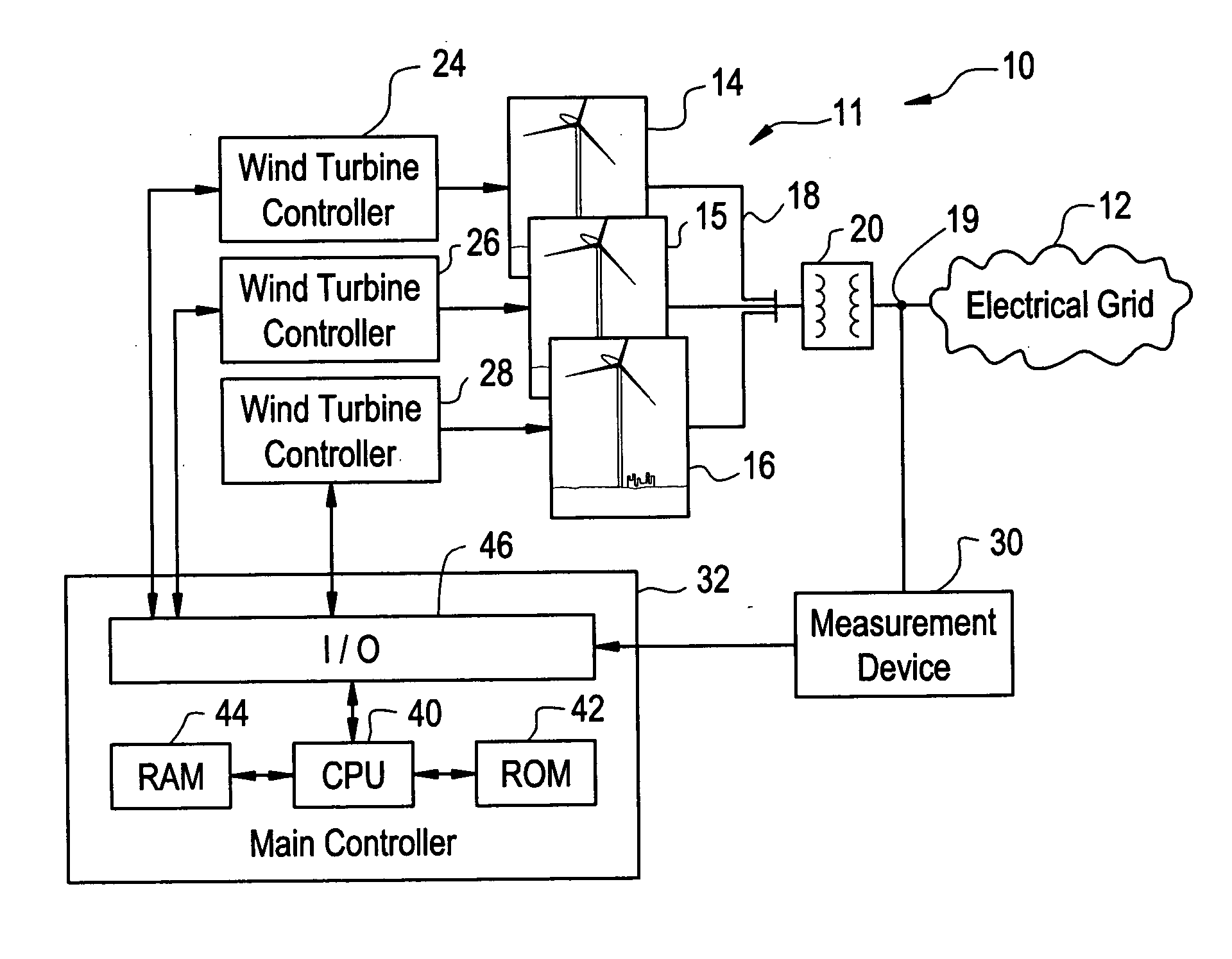
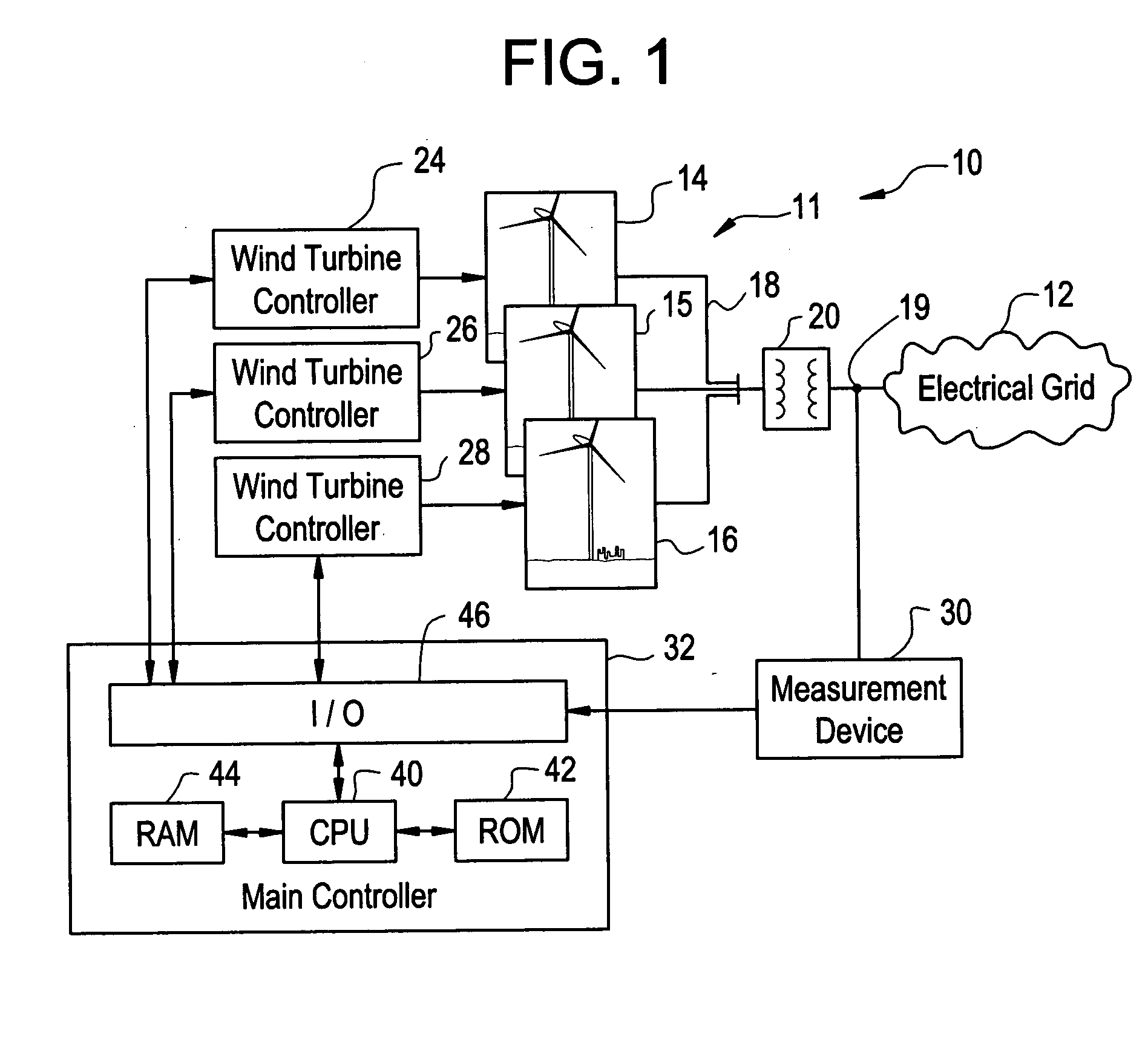
[0017] Referring to FIG. 1, an electrical power generation system 10 for generating electrical power is illustrated. The electrical power generation system 10 includes a wind farm 11 electrically coupled to an electrical grid 12. The electrical grid 12 is utilized to transfer electrical power from the wind farm 11 to electrical loads. In alternative exemplary embodiments, the electrical power generation system 10 can include at least one of micro-turbines, solar cell arrays, and conventional electrical generators, to replace the wind farm 11.

[0018] The wind farm 11 is provided to generate electrical power utilizing wind energy. The wind farm 11 includes wind turbines 14, 15, 16, a collector system 18, a transformer 20, wind turbine controllers 24, 26, 28, a measurement device 30, and a main controller 32. It should be noted that a number of wind turbines utilized in the wind farm 11 can vary. For example, the number of wind turbines in the wind farm 11 can be greater than three win...


PUM


Abstract

A system, a method, and an article of manufacture for controlling operation of an electrical power generation system are provided. The electrical power generation system has a plurality of electrical generators electrically coupled to an electrical grid. The method includes obtaining a first output parameter value associated with the electrical power generation system. The method further includes determining an error value indicative of a difference between the first output parameter value and a desired output parameter value. The method further includes determining a first gain value based on at least one of the first output parameter value and a time-varying operational parameter of the electrical power generation system. The method further includes determining a first power value based on the error value and the first gain value. The method further includes determining a second gain value based on at least one of the first output parameter value, the time-varying operational parameter, and a reference value. The method further includes determining a second power value based on the error value and the second gain value. The method further includes generating a desired power command for the electrical power generation system based on the first and second power values.

Description

BACKGROUND OF THE INVENTION [0001] A wind farm utilizes a plurality of wind turbines to generate electrical power. The wind farm is generally electrically coupled at a point of interconnection to an electrical grid. [0002] A control system is utilized to control the electrical output from a wind farm to meet utility requirements at the point of interconnection with an electrical grid of a utility company. However, a well-known problem associated with a conventional control system is that the control system is unable to maintain consistent dynamic performance of output voltage or reactive power at a desired level at the point of interconnection to the electrical grid, due to changing wind turbine conditions and electrical grid conditions such as (i) a variable number of turbines on line, (ii) changes in impedance of the electrical grid, and (iii) a switched capacitor or reactor banks. [0003] The inventors herein have recognized a need for an improved control system and method for con...

Claims


Application Information

Patent Timeline
IPC IPC(8): H02J1/00
CPCH02J3/16H02J3/50Y02E40/34Y02E10/763H02J3/386Y02E10/563H02J3/383F03D7/048H02J2300/28H02J2300/24H02J3/381H02J3/46Y02E10/56Y02E10/76Y02E10/72Y02E40/30Y02P70/50
Inventor DELMERICO, ROBERTCARDINAL, MARKMILLER, NICHOLASLIU, DAPENGYE, ZHIHONG
Owner GENERAL ELECTRIC CO
Learn More