

High pressure discharge lamp
a discharge lamp and high-pressure technology, applied in the direction of discharge tube luminescnet screen, discharge tube, gas-filled discharge tube, etc., can solve the problems of premature reduction of radiant light intensity, premature drying out of thorium (th) in the cathode, and flicker phenomenon
- Summary
- Abstract
- Description
- Claims
- Application Information
AI Technical Summary
Benefits of technology
Problems solved by technology
Method used
Image

Examples
Embodiment Construction
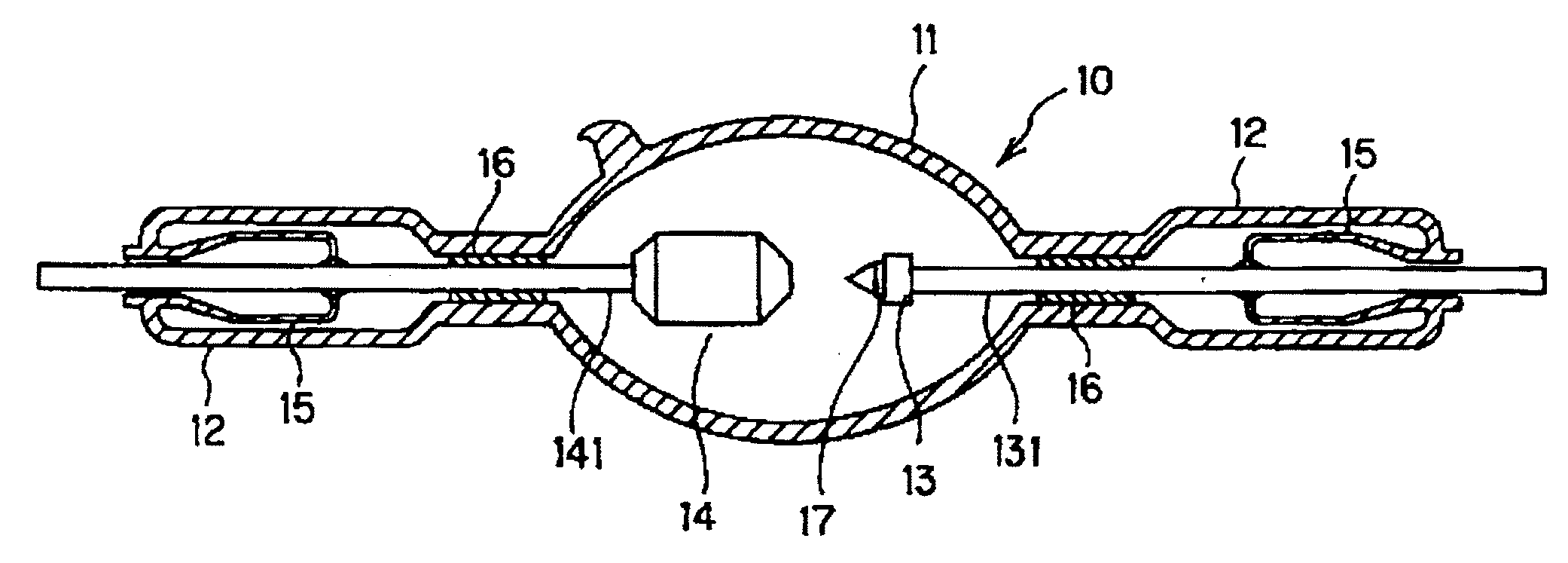
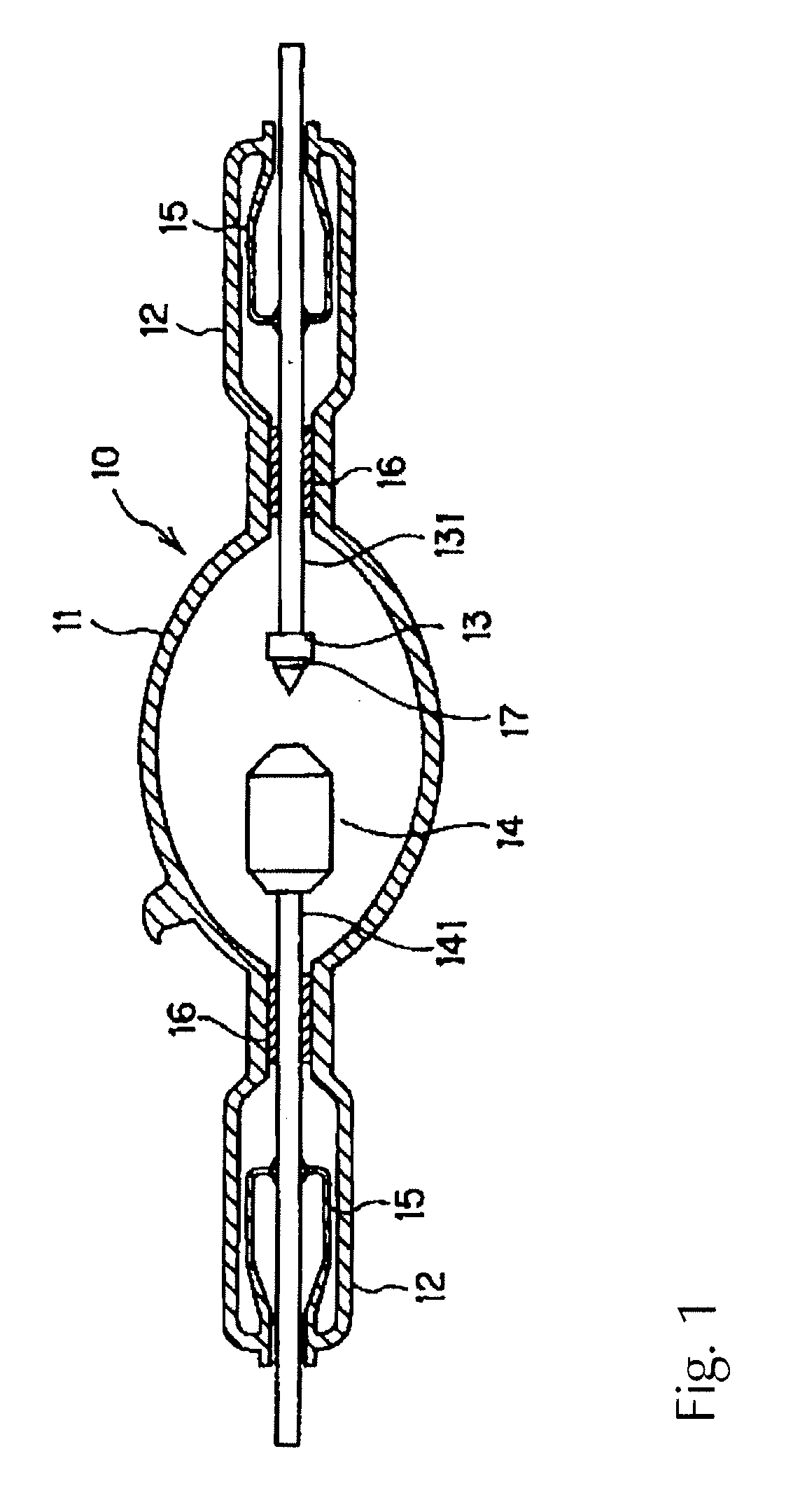
[0032]The high pressure discharge lamp 10 in accordance with the invention is described below using FIG. 1. For comparison purposes, parts of lamp 10 which correspond to like parts of the conventional lamp of FIG. 8 are identified by the same reference characters.
[0033]The high pressure discharge lamp 10 comprises a silica glass bulb which has an arc tube 11 and sealing parts 12. Furthermore, a cathode 13 and an anode 14 are arranged opposite each other in the arc tube 11.
[0034]The cathode 13 and the anode 14 are supported by tungsten electrode rods 131, 141, respectively, which are inserted into a silica glass cylindrical retaining body 16 which has a through opening which extends in a sealing part 12 in the axial direction. Furthermore, the electrode rods 131, 141, are sealed in the sealing part 12 by graded glass 15. The electrode rods 131, 141 extend outward from the outer end of the bulb and also act as outer lead pins which supply power to the cathode 13 and the anode 14. The ...
PUM
| Property | Measurement | Unit |
|---|---|---|
| temperature | aaaaa | aaaaa |
| pressure | aaaaa | aaaaa |
| diameter | aaaaa | aaaaa |
Abstract
Description
Claims
Application Information