Two step corner recess for secondary stray field reduction in a perpendicular magnetic recording head

a perpendicular magnetic recording and secondary stray field technology, applied in the field of current perpendicular to plane magnetic recording, can solve the problems of potentially erased stored data from the recording medium, the soft underlayer is extremely susceptible to being affected by magnetic fields, and the data is erased. to achieve the effect of increasing the lateral distance from the center of the structur

Inactive Publication Date: 2007-10-04
WESTERN DIGITAL TECH INC
View PDF22 Cites 10 Cited by
  • Summary
  • Abstract
  • Description
  • Claims
  • Application Information

AI Technical Summary

Benefits of technology

[0016] The present invention provides a magnetic structure for use in a magnetic head configured to prevent stray field writing in an adjacent magnetic medium. The magnetic structure has a centrally disposed, forward protruding portion that extends toward the air bearing surface (ABS) of the head. First and second wing shaped portions extend from the centeral, forward protruding portion. Each wing portion has an inner portion and an outer portion. The inner wing portion has a front edge that is recessed from the ABS by a recess distance that is substantially constant, and the outer wing portion is tapered so that its front edge is recessed from the ABS by an amount that increases with increasing lateral distance from the center of the structure.
[0017] The recess of the wing portions advantageously prevents stray field, writing. The constant recess of the inner wing portion advantageously prevents magnetic saturation near the center of the structure, while the backward taper (increasing recess) of the outer portion provides added protection against stray field writing by moving the outer corners of the structure away from the ABS.

Problems solved by technology

The magnetic medium 112 of a perpendicular recording system creates problems with regard to data erasure that are not generally encountered with longitudinal recording systems.
Because of its low coercivity and relatively large size, the soft underlayer is extremely susceptible to being affected by magnetic fields.
This can result in unwanted stray magnetic fields 108 collecting in the corners of the magnetic structure, which can potentially erase stored data from the recording medium 158.
Although magnetic structures such as magnetic shields and magnetic poles exhibit the problem described above, such magnetic structures are a necessary part of magnetic recording heads and cannot simply be eliminated.

Method used


Image

  • Two step corner recess for secondary stray field reduction in a perpendicular magnetic recording head
  • Two step corner recess for secondary stray field reduction in a perpendicular magnetic recording head
  • Two step corner recess for secondary stray field reduction in a perpendicular magnetic recording head

Examples


Embodiment Construction

[0027] The following description is of the best embodiments presently contemplated for carrying out this invention. This description is made for the purpose of illustrating the general principles of this invention and is not meant to limit the inventive concepts claimed herein.

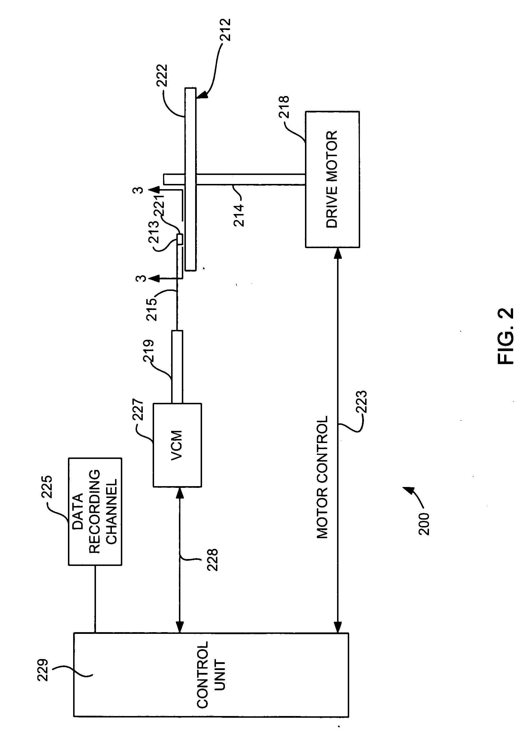
[0028] Referring now to FIG. 2, there is shown a disk drive 200 embodying this invention. As shown in FIG. 2, at least one rotatable magnetic disk 212 is supported on a spindle 214 and rotated by a disk drive motor 218. The magnetic recording on each disk is in the form of annular patterns of concentric data tracks (not shown) on the magnetic disk 212.

[0029] At least one slider 213 is positioned near the magnetic disk 212, each slider 213 supporting one or more magnetic head assemblies 221. As the magnetic disk rotates, slider 213 moves radially in and out over the disk surface 222 so that the magnetic head assembly 221 may access different tracks of the magnetic disk where desired data are written. Each sli...


PUM

PropertyMeasurementUnit
recess distanceaaaaaaaaaa
angleaaaaaaaaaa
magneticaaaaaaaaaa

Abstract

A magnetic structure for use in a magnetic head for avoiding stray field writing. The magnetic structure can be for example a magnetic shield or could be a magnetic pole of a write head and is particularly advantageous for use in a perpendicular recording system, because such perpendicular recording systems are especially susceptible to stray field writing. The magnetic structure includes a forward protruding portion that extends toward the air bearing surface (ABS) of the head also includes first and second wing portions that extend laterally from the forward protruding portion. The wing portions each have includes an inner constant recess portion, and an outer tapered portion. The inner constant recess portion of each wing prevents stray field writing while also preventing magnetic saturation, the outer tapered portions, which taper away from the ABS as they extend laterally outward, further prevent stray field writing by removing the outer corners of the shield away from the ABS.

Description

FIELD OF THE INVENTION [0001] The present invention relates to current perpendicular to plane magnetic recording and more particularly to novel magnetic trailing shield design to avoid adjacent track interference and more particularly to avoid wide angle track erasure (WATER) while also avoiding excessive magnetic flux in a center region of the trailing shield. BACKGROUND OF THE INVENTION [0002] The present invention is related to the following commonly assigned patent applications: NOTCHED SHIELD DESIGN AND POLE STRUCTURE WITH SLANTED WING FOR PERPENDICULAR RECORDING, application Ser. No. 10 / 976,479, filed Oct. 29, 2004; WINGED DESIGN FOR REDUCING STRAY MAGNETIC FIELDS, application Ser. No. 10 / 977,315, filed Oct. 29, 2004; WINGED POLE AND SHIELD STRUCTURE FOR REDUCING STRAY FIELD IN A PERPENDICULAR WRITE HEAD, application Ser. No. 10 / 971,478, Oct. 29, 2004; and STRUCTURE FOR STRAY FIELD REDUCTION IN A MAGNETIC HEAD, application Ser. No. 10 / 971,478, filed October, 2004. [0003] The h...

Claims


Application Information

Patent Timeline
Patent Type & Authority Applications(United States)
IPC IPC(8): G11B5/147
CPCG11B5/3116G11B5/1278
Inventor HSIAO, WEN-CHIEN DAVIDHSU, YIMINJIANG, MINGNIKITIN, VLADIMIR
Owner WESTERN DIGITAL TECH INC
Why Eureka
Try Eureka