
Pipe compression equipment

a compression equipment and pipe insulation technology, applied in the direction of packaging, manufacturing tools, packaging machine details, etc., can solve the problems of difficult loading of packages onto shipping vehicles, inefficient loading of packages, and inconvenient handling of packages, so as to reduce the damage of pipe insulation products, reduce the damage of products, and improve the efficiency of truck loading

Active Publication Date: 2021-07-29
JOHNS MANVILLE CORP
View PDF0 Cites 0 Cited by
  • Summary
  • Abstract
  • Description
  • Claims
  • Application Information

AI Technical Summary

Benefits of technology

The present invention provides a system and method for compressing and packing pipe insulation in a more efficient and uniform manner, with reduced damage to the packed insulation and improved truck loading efficiency. The system includes a compression member and a stacking bay with movable walls to adjust the lateral distance between them, while the method involves inserting the insulation into the stacking bay and moving the compression member to compress the insulation while adjusting the distance between the two walls. The technical effect is a more uniform and efficient packing of pipe insulation with reduced damage to the insulation products.

Problems solved by technology

Oftentimes, such techniques result in bundles of insulation that are not uniform in shape or size.
Additionally, the compressed pipe insulation is often damaged due to the extreme of vacuum applied to the insulation material.
The lack of uniformity of the packages of compressed pipe insulation also makes loading the packages onto shipping vehicles difficult and inefficient, as the various shapes and sizes of packages may be difficult to stack and / or otherwise arrange.

Method used


Image

  • Pipe compression equipment
  • Pipe compression equipment
  • Pipe compression equipment

Examples


Embodiment Construction

[0022]The subject matter of embodiments of the present invention is described here with specificity to meet statutory requirements, but this description is not necessarily intended to limit the scope of the claims. The claimed subject matter may be embodied in other ways, may include different elements or steps, and may be used in conjunction with other existing or future technologies. This description should not be interpreted as implying any particular order or arrangement among or between various steps or elements except when the order of individual steps or arrangement of elements is explicitly described.

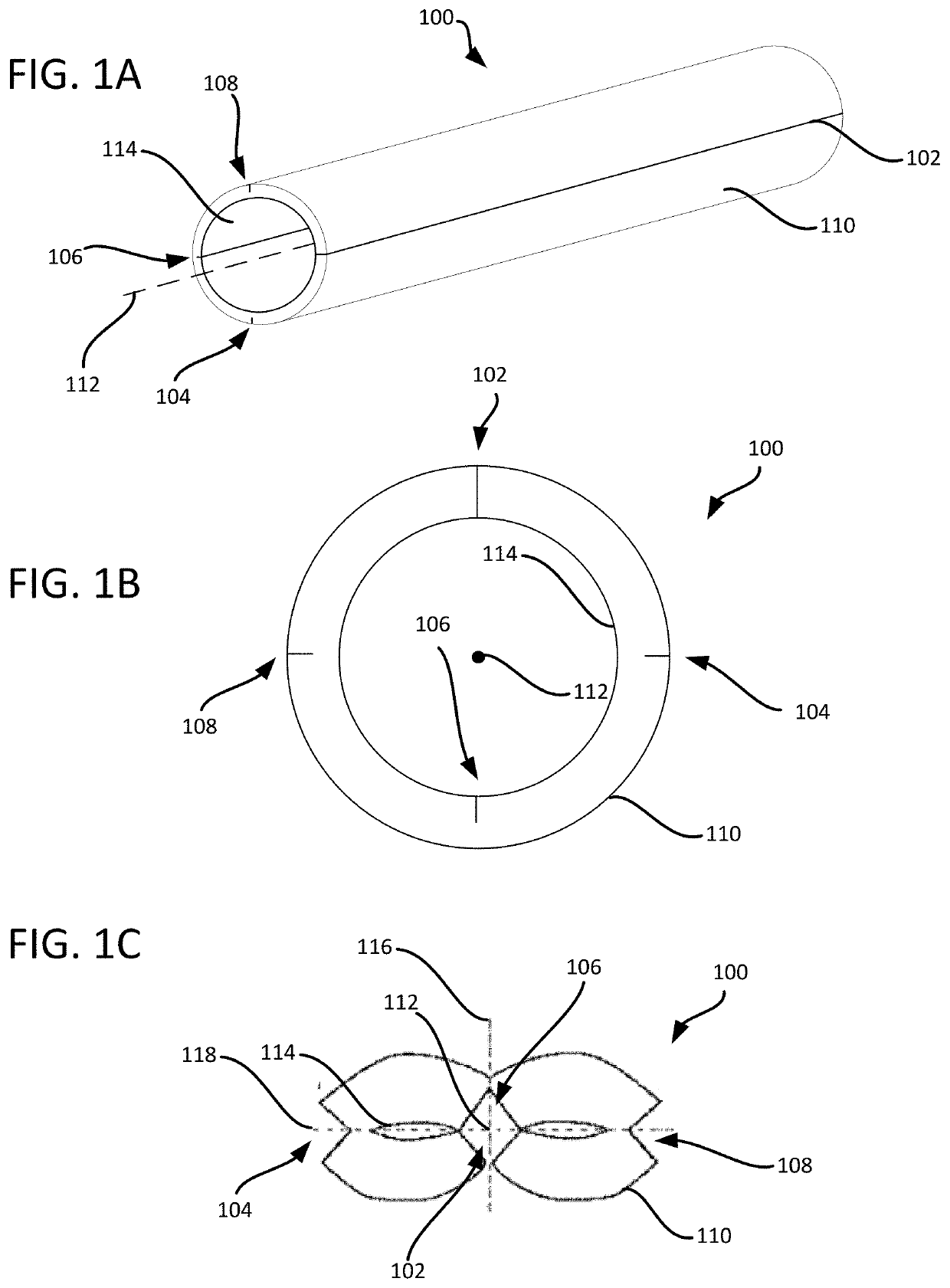
[0023]Embodiments of the present invention are directed to systems and methods of compressing and packaging pipe insulation. Embodiments provide solutions that enable pipe insulation to be packaged in manner that results in consistent and efficient sizes and shapes for shipment and / or storage without resulting in damage to the pipe insulation. Embodiments achieve such results by...


PUM


Abstract

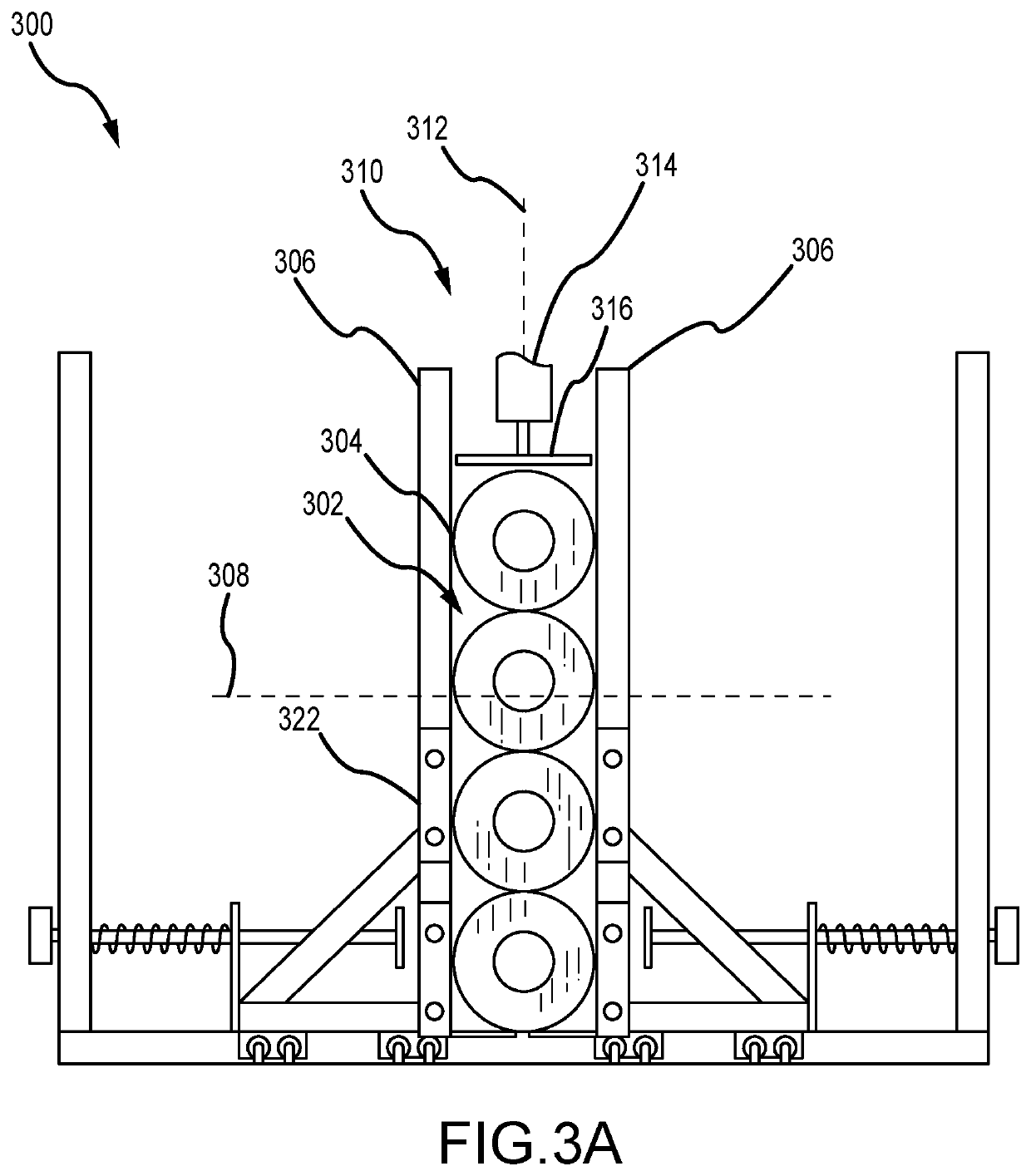
A system for compressing and packing pipe insulation includes a compression member that is movable along a first axis to compress pieces of pipe insulation. A stacking bay includes opposing walls that are spaced apart from one another. At least one of the two opposing walls is movable relative to the other of the two opposing walls along a second axis to adjust a lateral distance between the opposing walls to accommodate an increasing size of the pieces of pipe insulation along the second axis. The first axis is generally orthogonal to the second axis. A packing member that applies a force along a third axis to the pieces of pipe insulation after being compressed. The third axis is generally orthogonal to the first and second axes. The first axis is generally orthogonal to the second axis. The compression member is aligned with a space formed between the opposing walls.

Description

BACKGROUND OF THE INVENTION[0001]Existing compression and packing processes for pipe insulation typically utilize vacuum packaging techniques. For example, sections of insulation may be interleafed and then inserted into a plastic bag. A vacuum hose or other device is then used to remove air from the bag until the insulation material is compressed enough to allow a sleeve to be slid over the compressed insulation. Oftentimes, such techniques result in bundles of insulation that are not uniform in shape or size. Additionally, the compressed pipe insulation is often damaged due to the extreme of vacuum applied to the insulation material. The lack of uniformity of the packages of compressed pipe insulation also makes loading the packages onto shipping vehicles difficult and inefficient, as the various shapes and sizes of packages may be difficult to stack and / or otherwise arrange.BRIEF SUMMARY OF THE INVENTION[0002]Embodiments of the present invention are directed to pipe insulation, a...

Claims


Application Information

Patent Timeline
IPC IPC(8): B65B13/20F16L59/14B65B35/52F16L59/02
CPCB65B13/20F16L59/14B25J9/10F16L59/021B65B35/52B65B25/00B65B63/02B65B35/40B65B5/06F16L59/023B65B25/145B65B59/001B65B63/028B25J5/007
Inventor FELLINGER, THOMAS JOHNFREEMAN, JOSHDORSEY, JAYAMALAR
Owner JOHNS MANVILLE CORP
Learn More