Service quality management device and service quality management method

a service quality management and management device technology, applied in the field of service quality management devices and to a, can solve the problems of limiting the number of services provided to users, unable to apply to the ip network, and the difficulty in meeting the demands of maintaining the quality of service, so as to prevent the deterioration of the quality of the communication service and effectively utilize the network resources

Inactive Publication Date: 2007-10-04
FUJITSU LTD
View PDF19 Cites 31 Cited by
  • Summary
  • Abstract
  • Description
  • Claims
  • Application Information

AI Technical Summary

Benefits of technology

[0028] According to the present invention, it is possible to actualize the service quality management device that prevents the deterioration of the quality of the communication service provided on the network while effectively utilizing the network resources.

Problems solved by technology

This type of conventional acceptance control is to reject the acceptance if there are requests exceeding a present network transfer capacity for the service, but is not a scheme for improving the network transfer capacity for the service request.
In other words, the conventional acceptance control results in restricting a number of services provided to users in order to maintaining the quality of service.
The conventional acceptance control technologies having no alternative but to restrict a number of the provided service in order to maintain the quality of service are hard to meet these demands.
Moreover, the technology disclosed in Patent document 1 given above targets at a connection-oriented network as by MPLS (Multi-Protocol Label Switching) and therefore has a problem of being unable to be applied to the IP network.
The grasp of the demand information, however, needs observing all the pass-through packets in the routers within the network, resulting in a problem of being hard to actualize in a large-scale network.

Method used


Image

  • Service quality management device and service quality management method
  • Service quality management device and service quality management method
  • Service quality management device and service quality management method

Examples


operational example

[0080] An operational example of the service quality management device in the embodiment will hereinafter be explained with reference to FIGS. 7 to 12. At first, the initial network status and the initial demand state shown in FIG. 7 shall be assumed on the occasion of explaining the operational example.

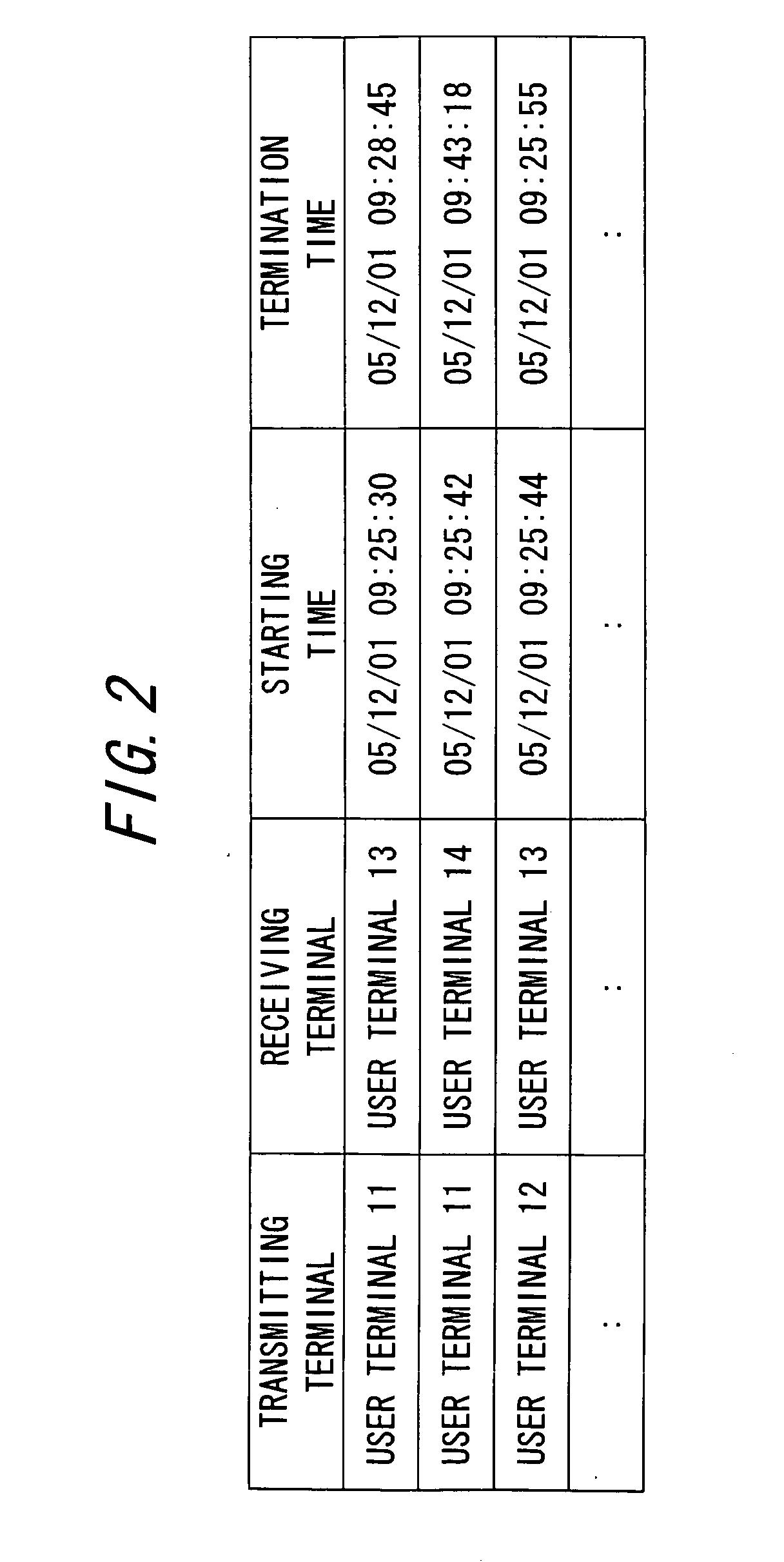
[0081] In the status illustrated in FIG. 7, the service demand collecting unit 101 acquires the connection log from the application server 21, and extracts the demand information on the communication service of the quality control target from the connection log. Further, the service demand collecting unit 101 estimates the traffic volume of each demand from the extracted demand information. The thus-extracted-and-estimated demand information is set in the demand information table. Herewith, three records about the demand from the access area A to the access area C (which will hereinafter be expressed such as the demand A→C), the demand from the access area A to the access area D (wh...

embodiment

Operational Effect of Embodiment

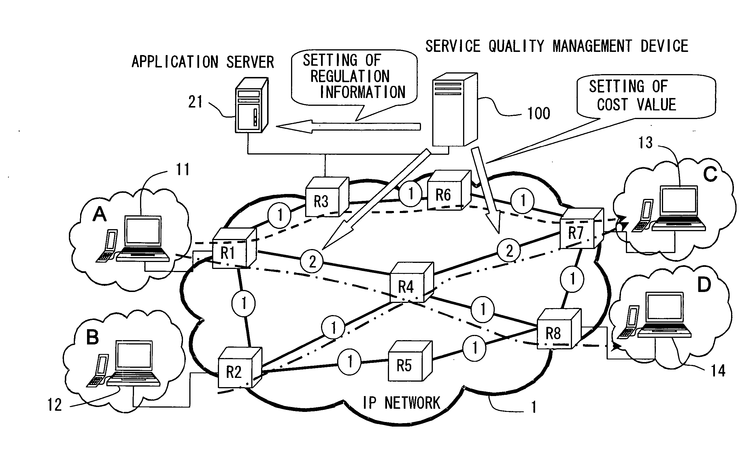
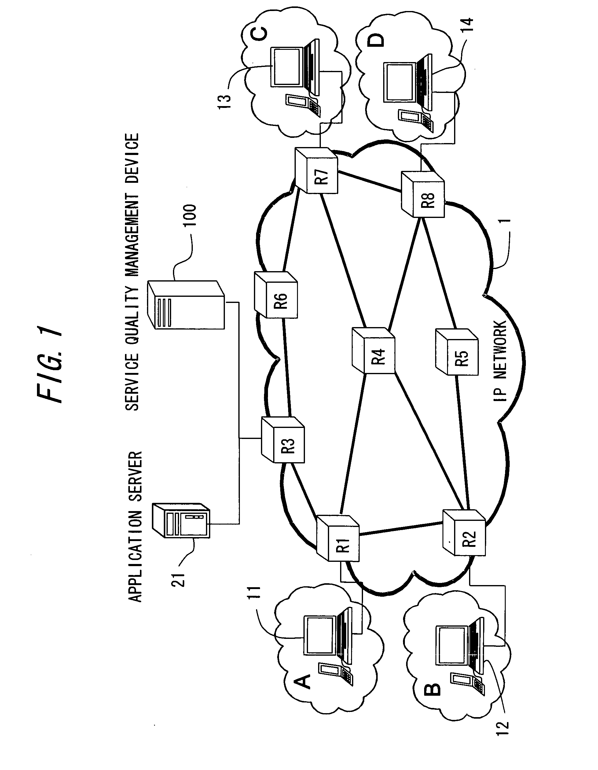
[0110] In the service quality management device according to the embodiment of the present invention, with respect to the management target IP network 1, the quality of the predetermined service is managed based on the information acquired by the service demand collecting unit 101 and by the topology collecting unit 105.

[0111] The service demand collecting unit 101 acquires the connection log from the application server21 and extracts the demand information on the communication service as the quality control target from this connection log. Further, the traffic volume for each demand is estimated from the extracted demand information. Moreover, the topology collecting unit 105 acquires the network configuration information from the routers R1-R8 configuring the IP network 1. The network configuration information contains information such as the topology information, the IP address associated with each link, the cost value of each link, the physical b...

modified example

[0121] The embodiment discussed above is that the control setup unit 108 automatically sets, in the network devices, the optimal cost value and the demand regulation information that are calculated by the control calculation unit 110. The service quality management device 100 according to the present invention is not limited to this configuration and can be operated as a desktop simulation device before being connected to the IP network 1. In this case, the demand information table set by the service demand information collecting unit 101 and the network configuration information table set by the topology collecting unit 105, may each be manually set by an operator, while the control setup unit 108 may also be controlled so as not to operate.

[0122] Even if done so, other functional units are still operable, so that the optimal link cost value and the demand regulation information are determined in the same way as the above and are set in the respective tables. This scheme, owing to...


PUM


Abstract

A service quality management device, preventing deterioration of a quality of a communication service provided on a network while effectively utilizing network resources by managing the quality of the communication, comprises an information acquiring unit acquiring service information containing information about each of sessions for the communication service and the network configuration information, an information generation unit generating a traffic volume of each of the sessions, a route determination unit determining a packet route for each of the sessions based on the respective information, a calculation unit calculating a traffic volume and a load of each of the links based on the traffic volume of each of the sessions and the packet route for each of the sessions, and a quality judging unit judging a quality of service actualized by each of the sessions based on the calculated load of each of the links.

Description

BACKGROUND OF THE INVENTION [0001] 1. Field of the Invention [0002] The present invention relates to a service quality management device and to a service quality management method that manage a quality of a communication service provided on a network. [0003] 2. Description of the Related Art [0004] In a case where an application server provides a predetermined service to other nodes (user terminals etc) on the network, it is general to conduct acceptance control as control for maintaining the quality of the service to be provided. The acceptance control connoted herein is that it is judged based on a predetermined condition whether a request for the service can be accepted or not. For instance, when a SIP (Session Initiation Protocol) server provides a VoIP (Voice over Internet Protocol) service, the quality of service (QoS) is maintained in a way that prevents simultaneous connections for a fixed or greater number of calls as requests for the service by an acceptance control functi...

Claims


Application Information

Patent Timeline
Patent Type & Authority Applications(United States)
IPC IPC(8): H04J1/16H04L12/56H04L12/24H04L12/70
CPCH04L41/5009H04L41/5096H04L45/302H04L45/125H04L45/123
Inventor YAMADA, HITOSHIYAMADA, AKIKO
Owner FUJITSU LTD
Why Eureka
Try Eureka